Part 2 looked at two types of RF/microwave filters, but there are many more, including ceramic coaxial filters and helical filters. They are discussed in this part.
Microstrip filters
Microstrip filters are built as a carefully defined pattern on a PC board. There is almost no limit to the filter designs which can be built using a PC board pattern cut with hairpin curves, straight lines of varying widths, and other geometric arrangements singly or in combinations. Some microstrip bandpass filters simultaneously handle two or more frequencies, and also include notch filters as well, which would be difficult or impossible using other RF/microwave filter structures. What makes envisioning these filters and verifying them before actually making them is sophisticated EM-field modeling software, which analyzes both their basic characteristics as well as the sensitivity of critical dimensions.
For example, consider a miniaturized ultra-wideband (UWB) microstrip bandpass filter with wide passband (Figure 1). This filter was developed based on a modified multiple-mode resonator, which is formed by transversely attaching three pairs of non-uniform and folded stubs with lowpass and highpass sections. Both sides of the high-impedance section are linked with two feed lines via direct-coupled lines, resulting in a UWB bandpass filter.
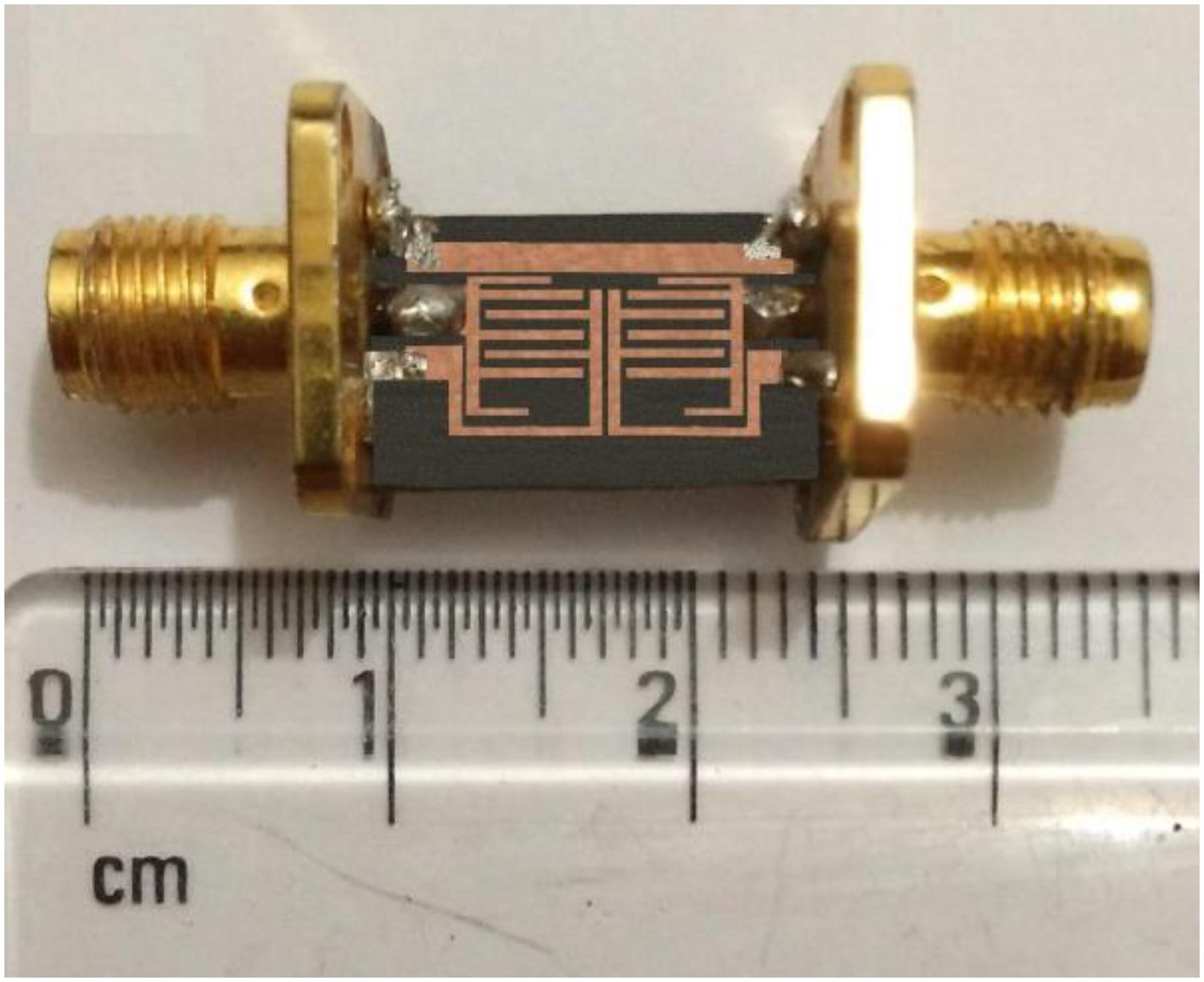
The filter provides 7 GHz passband between 2.5 and 9.5 GHz with approximately –0.5 dB insertion loss, –35 dB minimum return loss at 6.85 GHz, linear phase over the passband, and 110% of fractional bandwidth at –3 dB. The computed group delay variation in the passband for the filter is 0.02 nsec. The overall dimension of the filter is 10.7 mm (length) × 3 mm (width) × 1.6 mm (thickness).
As these microstrips are built on a PC material substrate, they are low cost and physically flat but tend to have a high insertion loss and low power-handling capability. The filter can be fabricated as a separate device on its PC board (as in the figure), or it can even be incorporated onto the product’s PC board for a lower cost. In that case, however, any nearby components must be incorporated into the EM-field model as they will affect the filter performance, and guard areas on the board are often required, thus adding to the overall footprint.
Another feature of microstrip technology is that it can also be used to create antennas, either in conjunction with or unrelated to a microstrip filter. Further note there are also PC-board constructions called “striplines,” These are RF transmission lines, stubs, and other functions which can be created to provide almost any impedance or RF energy path using precisely dimensioned etches in the internal layers of a PC board; again, these can be paired with or unrelated to a microstrip filter.
Q is typically in the range of several hundred. In many cases, standard FR-4 PC-board substrate is inadequate due to its inconsistent dielectric properties, so higher-cost board substrates must be used instead. Microstrip filters are attractive because they seem to represent almost “something for nothing” – no separate item on the BOM in many cases and they can provide filtering configurations which are otherwise very difficult or impossible to achieve – but, of course, there is a performance and real-estate cost. And the final specification may not be adequate for the application.
Ceramic coaxial filters
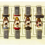
These coaxial filters are a combination of distributed and lumped elements. They use ceramic resonators functioning as miniature coaxial cables, which are shorted at one end and open at the other, somewhat similar to cavity and comb filters (Figure 2). However, the energy is coupled from one resonator to another using a ceramic substrate coated with a conductor and which acts as a coupling capacitor. The dimensions of the resonators set the center frequency, while the dimensions of these coupling capacitors establish the filter bandwidth.
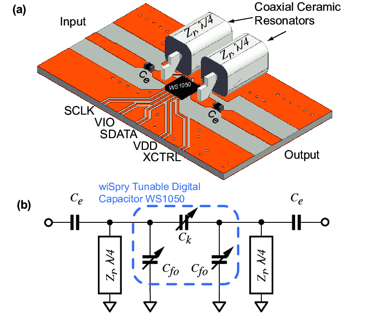
These filters have moderate insertion loss and size and can handle tens of watts, depending on the sizing of their materials and components. They typically have Q in the 200-500 range and a low to moderate cost.
Helical filters
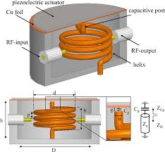
Like the ceramic coaxial filter, the helical filter uses a combination of lumped and distributed elements. However, unlike that filter, it uses inductors to couple energy from one element to another and does so via air gaps (Figure 3). The helical filter has low insertion loss, is relatively large, and can handle up to 100 W and more due to its use of inductors; higher-power units use tubing instead of wire and can go into the kW range. Q is very high, up to about 1000, but so is their relative cost.
Looking to the future
While filter design is a combination of art and skill with a long history, and it is also evolving due to two forces driving and reinforcing each other. On one side, there is a need for smaller, higher Q, more precise filters for mass-market applications such as smartphones (even more stringent for 5G) and wireless connectivity such as Wi-Fi, which is trending to higher frequencies.
At the same time, advances in solid-state MEMS-type components are fostering the development of tiny, trimmed, fully characterized filters which provide very good performance at lower-power levels, which is where so much of the market demand is, along with acceptable tradeoffs. We are already seeing MEMS-derived techniques used for transmit/receive (TR) switches, in signal paths, and in filters targeting specific applications and which meet the demands of these situations. In addition, highly accurate positioning via piezoelectric devices is also being added to allow precise mechanical adjustments and thus tuning. The combination of MEMS and piezoelectric technologies, and new topologies, supported by advanced electronic/mechanical modeling and simulation tools is leading to bandpass (and other) filter advances in performance specifications, size, and cost.
EE World References
- Basics of bandpass filters
- What are the functions and principles of S-parameters (Part 1)?
- What are the applications and measurements of S-parameters? (Part 2)
- Using the Smith chart for Impedance matching, Part 1
- Impedance matching and the Smith Chart, Part 2
- Printed Circuit Boards, Part 1: Context and phenolic boards
- The basics of FR-4 Printed Circuit Boards
- Printed Circuit Boards, Part 3: Vias and multilayer boards
- Printed Circuit Boards, Part 4: Beyond FR-4
- Filters, Part 2: SAW and BAW devices for RF
External References
- Knowles Capacitors, “Microstrip Filters Deliver Small Size at High Frequencies”
- Skyworks Solutions, Inc., “Glossary of Terms for Coaxial Resonators and Coaxial Inductors”
- Skyworks Solutions, Inc., “Measuring SRF and Q of Coaxial Resonators”
- Skyworks Solutions, Inc., “Characteristic Impedance of Coaxial Resonators”
- Johanson Technology, “SRF & PRF for RF Capacitors”