Part 1 of this FAQ looked at the basic specifications of noise factor and noise figure, widely used in RF/microwave system and circuit analysis to predict and assess both requirements and performance. This part looks at the additional parameter of noise temperature, as well as the impact this parameter has on system performance. It also looks briefly at making these noise measurements.
Q: I understand the idea of noise figure, but what’s “noise temperature?”?
A: The term “effective input noise temperature” (Te) or simply “noise temperature” is used in place of noise figure, especially for applications which involves satellite and similar “sky pointing” systems. In this case, Te is the equivalent temperature of a source impedance into a perfect (noise-free) device that would produce the same added noise.
Q: How does noise temperature relate to noise factor F and noise figure NF?
A: A simple equation relate the them:
For noise factor: Te = T0 (F – 1), where T0 is 290 K
For noise figure: Te = T0 (10 (NF/10) – 1), again, where T0 is 290 K
Q: Why do we even need a “noise temperature” number?
A: When dealing with terrestrial communications, we don’t. But when dealing with “extra-terrestrial” links, it is a useful design parameter.
Q: How so?
A: Let’s back up for a moment. In the high-frequency (HF) range of 3 to 30 MHz, atmospheric and man-made noise are high. In the very high frequency (VHF) range (30- 300 MHz), the noise levels start to drop and go down to around 1000 K in quiet, non-urban locales. As frequencies increase to the microwave region and multi-GHz zone, the primary noise sources are the ground (300 K, approximately) and the sky, at 3.2 K (called Cosmic Microwave Background or CMB, the residue of the “Big Bang”). An antenna pointed at the horizon has a noise temperature of a little over 150 K, as the Earth contributes half of this temperature while the sky contributes little. An antenna which is pointed only at the sky will see a noise temperature of around 15 to 25 K, a combination of the CMB reading and some stray ground temperature.
Q: Does a small change in NF correspond to a small change in noise temperature?
A: Not where NF must be low, as it is for most components in the front end of an off-Earth antenna and link. The Table shows noise figure versus corresponding noise temperature in this region; note the large nonlinear effect due to the logarithmic function:
| Noise Figure | Noise Temperature | ||
| 0.2 dB | 13.7 K | ||
| 0.4 dB | 28.0 K | ||
| 0.6 dB | 43.0 K | ||
| 0.8 dB | 58.7 K | ||
| 1.0 dB | 75.1 K | ||
| 1.5 dB | 119.6 K | ||
| 2.0 dB | 169.6 K | ||
| 2.5 dB | 225.7 K | ||
| 3.0 dB | 288.6 K | ||
| 6.0 dB | 864.5 K | ||
Q: What’s the impact of noise added by the front-end amplifier, usually referred to as the LNA (low-noise amplifier)?
A: Calculations show that the front-end stage is most critical to system performance. For example, a system at 1 GHz using a good (but not great) LNA with a NF of 1 dB (75 K) has a total noise temperature of around 95 K. Replacing that LNA with a better one having 0.4 dB NF (28 K) reduces the noise temperature to 48 K, a 3-dB improvement in SNR.
Q: How do you use NF to calculate system performance?
A: The goal of an RF/microwave receiver is to capture a weak signa with adequate SNR so that it can be demodulated and decoded to provide satisfactory BER. The received signal at the antenna must be amplified as it is too weak to be useful as received. Any noise added by the front-end LNA (and there is always some) degrades received SNR and that degradation can’t be reversed, regardless of the amount of subsequent simplification, Figure 1. Boosting the signal at the front end while adding as little noise as possible is key, as it allows for additional gain followed by signal processing and extraction, with little BER penalty.
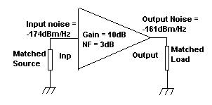
For this reason, highest-performance receivers actually supercool the LNA (often down to near absolute zero, 0 K) to minimize random thermal noise, and some systems even cool the transmission cables between the LNA and the next input stage since they, too, contribute thermal noise. If the noise contributions of the LNA (and cable) are low enough, any noise added by the second and subsequent stages will be negligible in terms of system performance and BER, Figure 2.
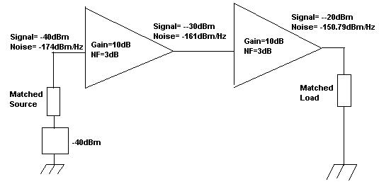
Q: How are these calculations done?
A: To determine the overall noise figure of thee system, the individual noise figures and gains of each system block or stage must be known. The References below explain how this is done.
Q: With all this talk of noise, how is it measured?
A: First, it is not at easy to measure this noise accurately; it requires the right equipment, setup, calibration, and careful control of fixtures, cables, and more. The most-common way to measure noise begins with a calibrated noise source, a unit that can provide two known levels of noise. The two levels of noise are applied to the DUT input and then the change in output power is measured. The construction, development, and use of this calibrated noise source is a major subject it itself. Most test systems today use a special, low-capacitance diode that generates noise when reverse biased, but there are other implementations as well.
The subject of noise, noise factor, noise figure, noise temperature, noise source, noise measurements and related topics are complicated, both in analytical terms and in actual physical realization. Due to its importance, noise and related issues have been extensively studied and analyzed, and solutions have been constantly enhanced as user needs become more challenging, frequencies in use increase, data rates increase, and overall system demands increase.
The references below provide further insight and depth to this complicated yet very important (and increasingly so) topic and its many perspectives. Always remember: if there was no noise, then RF/microwave design would be far, far easier, as noise in its many manifestations is an issue which permeates nearly all aspects of a design, with an enormous ripple effect on design architectures, components, and physical realization.
References
- Keysight Technologies, “Fundamentals of RF and Microwave Noise Figure Measurements”
- National Instruments, “Noise factor, noise figure, and noise temperature”
- IEEE Microwaves 101, “Noise Temperature”
- Sujeong Lee, “Noise Power, Noise Figure, and Noise Temperature”
- Satellite Signals Ltd, “Noise temperature, Noise Figure (NF) and noise factor (f)”
- QSL Net, “Understanding Noise Figure”