Part 1 of this FAQ looked at the basic role and function of the RF power amplifier (PA). This part looks at some of the factors to consider when looking at possible PA devices. It is not a detailed run-through of the many parameters which characterize PAs, including many which are unique to the PA function.
Q: What are the usual top-level concerns when doing the initial consideration of possible PAs?
A: There are four factors: output power, gain, operating frequency, and efficiency. If the PA under consideration falls short on any of these four, it is likely unsuitable or will require compromises on system performance.
Q: Start with output power — what’s that?
A: That’s easy to understand: it is the maximum amount of output RF power that the PA can develop at the desired frequency, while staying with specifications, given the proper mounting, heat sinking, and even modulation waveform. It is expressed in watts or dBm (dB reference to 1 mW).
Q: What about gain?
A: Again, relatively easy. Gain indicates how much of a “boost” the PA can provide, again at a specified frequency. It is the ratio of input power to the PA and output power from the PA and is expressed in dB. In some cases, the PA can provide the desired amount of output power, but does not enough gain to make use of that potential output from the much-smaller input signal. In such cases, a preamplifier is used between the low-level input-stage signal and the PA, to bring the PA input up to the needed level.
Q: Frequency seems obvious; is there anything special to know?
A: Yes, it is obvious, but the PA performance must be defined at the frequency and bandwidth of interest. Some PAs are optimized in terms of gain, power, and other factors to perform well at a single frequency or across a very narrow band. Others may provide performance which is not quite as impressive but can do so across a wider band, and so can be used for wideband applications. For example, a single Wi-Fi PA many need to work only at 2.4 GHz band or at 5.2 GHz band (the two most-common assigned ranges), but not at both; or it may need to be a dual-band PA. Therefore, the designer must choose between using two PAs (one for each band) or a single, wider-band PA which may have somewhat reduced specifications across the two bands.
Q: Is efficiency a single number?
A: No, that would be too easy. Instead, it is a function of the operating frequency, of course, but also the signal type, such as pulse versus CW (continuous wave), and modulation type. Efficiency is almost always a concern because it affects run time and battery life (in many designs such as smartphones, the PA is the largest consumer of DC power), and it affects thermal issues and how much power (heat) must be dissipated by the system.
Q: All other factors being equal, is it best to choose the highest-efficiency PA?
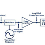
A: Not necessarily. First, all other factors are rarely equal between a lower-efficiency and a higher-efficiency PA. Second, a higher-efficiency PA may be more costly and larger. Third, the PA efficiency is a function of signal level and type, so some single-band designs may choose to go with two PAs: one which is efficient at lower power (and disabling the other one), and with a seamless transition to one which is less efficient at lower power better suited for higher power. One design based on this scheme is called a Doherty amplifier (Figure 1), and while it does work and can work well, the design and details of implementation have subtleties and requires great care in component selection, topology details, and operation to ensure a smooth and distortion-free transition between the two PAs.

Q: Speaking of distortion, what about distortion in its various forms?
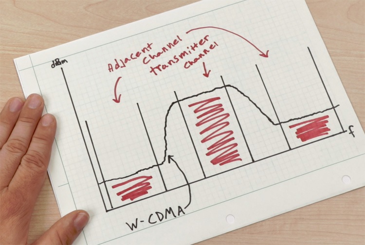
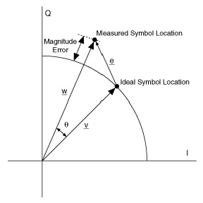
A: This is a very difficult factor to “nail down” as it depends on so many operating conditions. Among the many metrics are compression point and intercept point (for CW signals), adjacent channel power ratio (ACPR), (Figure 2), and error vector magnitude (EVM), (Figure 3) (for digitally modulated signals), along with parameters such as spur free dynamic range (SFDR).
Q: Is that all there is to distortion?
A: No, there are many other legitimate and useful measurements of linearity and distortion, and deciding which ones to use and how much weighting to give each is part of the design process, the PA modeling, and “secret sauce” of RF PA selection. Further, there are ways to improve the linearity and distortion of a PA by using feedback, pre-distortion, and feed-forward techniques, but these add complexity and cost. In many cases, the improvement effort is worthwhile because it enables better performance or the use of a less-expensive, lower-performance PA.
Q: How do you pick the right PA?
A: The choice of the “best” PA for a given application s not a simple one. As with many engineering designs, it involves tradeoffs and compromises among many factors such as parts cost, design complexity, circuit stability, sensitivity to component tolerances, and more. Most PA vendors provide tested and fully characterized reference designs which are a major help in a given high-volume or common application. Even if your application is instead unique or a niche, these reference designs can serve as good starting points.
References
- What’s The Difference Between GaAs And GaN RF Power Amplifiers?
- Impedance matching and the Smith chart, Part 1
- Impedance matching and the Smith Chart, Part 2
- The Doherty Power Amplifier
- RFMD, Doherty Power Amplifier Design
- Mini-Circuits AN-60-038, Amplifier Terms Defined
- AR Modular RF, 5 Steps to Selecting the Right RF Power Amplifier