Part 1 of this FAQ introduced some of the basic issues related to the measurement of RF power, which is a primary parameter in most RF designs. Part 2 continues the discussion, looking at RF waveforms and sensors.
Q: The term “power” is fairly broad; what are the specifics?
A: There are actually several basic power measurements which engineers need (note: these are somewhat simplified descriptions; in reality, nothing in the RF power world is simple):
- continuous wave (CW) power, which is the power of an unmodulated carrier;
- average or RMS power, which is the power measured over a longer time period, and so the effects of modulation are averaged out;
- peak power, which is the highest power level reached by the signal; this takes into account the effects of modulation of the RF carrier;
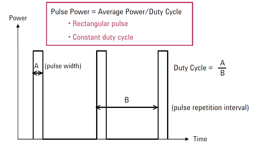
- pulse power, which is the average power divided by the duty cycle, Figure 1.
Different applications or aspects of a given design will prioritize one or more of these power metrics along the signal chain.
Q: What techniques and sensors are used for RF power measurements?
A: There are many sensor options, and each has pros and cons with respect to measuring a given signal, bandwidth, dynamic range, and power metric. They are divided into direct and indirect methods.
Q: What is “direct sensing”?
A: In direct sensing, the RF signal is applied to a load element which converts the RF to a more easily measured DC value. This conversion is usually implemented close to the signal source via a small converter probe – the RF power sensor – which is attached to the device under test.
Q: How is direct sensing actually implemented?
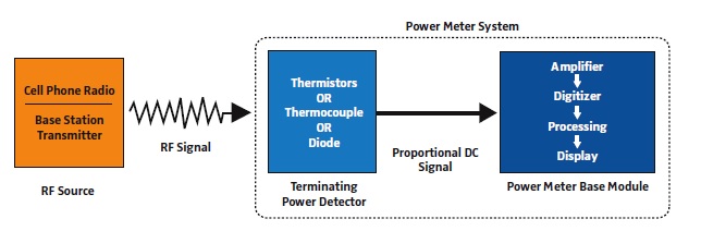
A: Two probe types are commonly used: a thermal probe (thermocouple, thermistor) which measures the heating effect of the RF power on a sensing element; and an RF detector (such as a diode), which rectifies (detects) the signal and develops a DC voltage proportional to the signal amplitude, Figure 2.
Note that there are several ways to build both the heating sensor and the RF detector, and each way offers different performance attributes and match to RF signal modulation and other characteristics. It’s a technically complex subject.
Q: What about indirect methods?
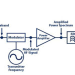
A: In most indirect approaches, the signal being measured is conveyed to the test instrument via a cable, processed, the amplitude is measured, and then the amplitude reading is converted to a power value.
Q: How is this done?
A: Two ways. In the older technique, a receiver with adjustable bandwidth tunes the signal and then measures its amplitude. In newer systems, RF sampling is used where the RF signal is treated as if it was a baseband AC signal and is directly digitized; the samples are then numerically processed. Doing sampling requires high-performance, wideband, fast-response A/D converts and is both expensive and has limits, but can be very accurate and versatile.
Q: What are some of the specifications to evaluate when considering an RF power-measurement system?
A: Among the factors to assess are:
- maximum frequency that can be measured (up to how many GHz?);
- minimum frequency (down to DC or down to several hundred MHz?);
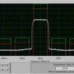
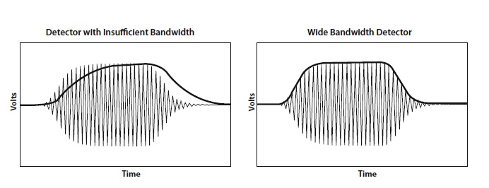
- sufficient bandwidth (insufficient bandwidth results in measurement errors, Figure 3); as well as wideband or selectable narrowband (you might need just one mode or both);
- dynamic range (a representative specification is the measurement of RF power from -80 dBm to +30 dBm);
- suitability of performance for average, peak, and pulse waveforms, as well as advanced forms of modulations;
- overall accuracy and calibration requirements, if any;
- interface to the test of the T&M system.
Q: What is meant here by “interface”?
A: Traditional RF sensors produced an analog voltage corresponding to the power being sensed and measured, and this analog voltage was conveyed to a test instrument for additional analysis and display. In recent years, the trend has been to put more functionality in the sensor assembly itself, such as a USB port. This front-end assembly then interfaces to a PC or other general-purpose instrument with appropriate application-setup and -analysis software plus graphical displays.
Again, the entire issue of RF power measurement is an extremely important one, but is also a complex one, with many issues related to frequency, bandwidth, waveform being measured, and other factors. The references cited at the end are just a few of the available resources which can be reviewed for more insight into this complex and somewhat confusing topic.
References
- Agilent (now Keysight) Technologies, “Power Measurement Basics”
- Agilent (now Keysight) Technologies, Application Note 64-1B, “Fundamentals of RF and Microwave Power Measurements”
- National Instruments, “5 RF Transmitter Measurements Every Engineer Should Know”
- Boonton/Wireless Telecom Group, “Principles of Power Measurement”