Part 1 of this FAQ looked at the venerable electromechanical RF switch – still widely used in some applications, where it is the only viable option—and the use of PIN diodes as RF switches. This part looks at analog and MEMS-based switches.
Q: What is an analog switch?
A: It’s conceptually straightforward: in basic form, it’s a three-terminal analog device with an input, output, and control line (plus power and ground, of course). The control line is used to turn the switch from on (conducting) to off (non-conducting) mode.
Q: Is this an ohmic on/off contact?
A: No, it’s analogous to turning a transistor (bipolar or FET) on and off, and there is still a leakage path.
Q: What’s so special about an analog RF switch? After all, basic analog switches have been around “forever.”
A: The function has been around but devising analog processes, and topologies that could handle RF frequencies with suitable specifications has been a challenge.
Q: What are the potential benefits of an analog switch? The drawbacks?
A: Advantages include size, switching speed, the power required, and cost. The disadvantages are that insertion loss and isolation may not be as good as needed – but that is rapidly improving.
Q: Are analog switches limited to basic SPST of SPDT configurations?
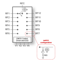
A: No, there are other configurations available. For example, the PE42412 from pSemi/Murata (formerly Peregrine Semiconductor) uses their UltraCMOS process, a patented advanced form of silicon-on-insulator (SOI) technology, plus their HaRP technology to create an SP12T RF switch which functions from 10 MHz to 8 GHz (Figure 1). It targets filter-bank switching and RF signal routing in wireless infrastructure applications. A four-bit digital code “steers” the input to the desired output.
Q: What are the key specifications of this switch?
A: It provides typical isolation of 39 dB and insertion loss of 1.3 dB, both at 6 GHz, switching time of just 232 nsec, and can handle up to 33 dBm (CW). It’s also tiny; housed in a 32-lead 5 × 5 mm QFN package.
Q: Is 10 GHz and below the upper limit for these analog switches?
A: No, recent process and design improvements, plus anticipated market needs, have pushed analog switches to much-higher frequencies.
Q: For example?
A: The ADRF5046 from Analog Devices, released in May 2019, is a single-pole, four-throw (SP4T) device for signals from 100 MHz to 44 GHz (Figure 2). The reflective switch design has an insertion loss of 1.5, 2.5, and 3.0 dB at 18, 40, and 44 GHz, respectively, along with isolation of 46, 33, and 31 dB at those frequencies.
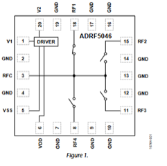
It includes integrated drivers allowing for a simple CMOS/LVTTL-compatible control interface, where two digital-control inputs establish the RF path. The switch design is bidirectional with equal power-handling capabilities in each direction of 27 dBm. The RF ports of this switch, in a 3mm × 3mm LGA package, are internally matched to 50 Ω – an important consideration in RF circuits.
Q: What about MEMS technology for switches? It would seem to be the equivalent to the electromechanical switch but in a tiny, low-cost IC form.
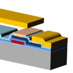
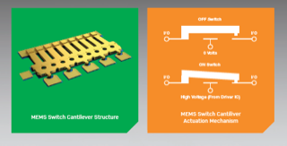
A: MEMS technology certainly has the potential to emulate an electromechanical RF switch. By using metalized contacts on a cantilever beam and moving (actuating) the beam using an electrostatic field, the beam contact can physically connect with a matching contact on the die.
Q: Do these switches exist?
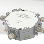
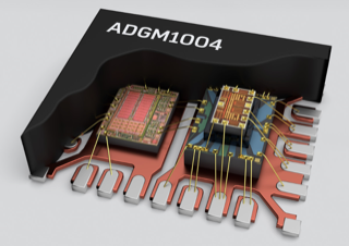
A: Yes, among them is the recently introduced ADGM1304, also from Analog Devices, a 0 Hz/DC to 14 GHz, single-pole, four-throw (SP4T) MEMS switch with integrated driver (Figure 3). This two-chip, co-packaged device features insertion loss of 0.26 dB and isolation of 24 dB (both typical at 2.5 GHz), and on-switching time of 30 μsec. The principle is simple, but the execution is difficult, of course, and the final device is rated for 500 million to one billion cycles without performance degradation.
Q: Why isn’t this a monolithic device?
A: The processes needed for the MEMS side and the electronic drive are very different. The device operates from a single, 3-V supply, but the electric field required to actuate the cantilever needs about 70 V. To make the 70-V issue “invisible” to the user, the switch has a DC/DC charge pump as a driver co-located with the MEMS die itself, all housed in a 5 mm × 4 mm × 0.95 mm LFCSP package (Figure 4).
This FAQ has briefly discussed the four widely used RF switch technologies, each with different capabilities and attributes. All are still in current use and will be so for the foreseeable future. As mass-market RF systems move to higher frequencies in the tens of GHz, the relative market share of these switch technologies switches may change, but in ways we can’t predict, as it also depends on how their technologies evolve and advance as well.
References – EE World
- Specialized diodes, Part 2: Varactor, Gunn, and PIN diodes
- SPDT PIN Diode Switches cover 10 MHz to 67 GHz range
- High-power SPDT RF switches handle up to 6 GHz
- High-throw count RF switches span 9 kHz – 8 GHz range
- FAQ: What is a charge pump, and why is it useful? (Part 1)
- FAQ: What is a charge pump, and why is it useful? (Part 2)
- Working with higher voltages, Part 1: Voltage boosters
References – General
- Wikipedia, “RF Switches”
- Microwave Communications Laboratories Inc, “Electromechanical Switches”
- Skyworks Solutions, Inc, “PIN Diode Basics”
- Microsemi Corp, Micronote 701, “PIN Diode Fundamentals”
- Keysight Technologies, “RF & Microwave Electromechanical Switches”
- pSemi Corp/Murata, PE42412 Data Sheet
- Analog Devices, ADRF5046 Data Sheet
- Analog Devices, ADGM1304 Data Sheet
- Analog Devices, “MEMS Switch Technology: Breaking New Ground”
- Analog Devices, “The Fundamentals of Analog Devices’ Revolutionary MEMS Switch Technology”
- Analog Devices, ”Analog Devices Makes MEMS Switch Technology a Commercial Reality”
- Infineon, “PIN diodes in RF switch applications”