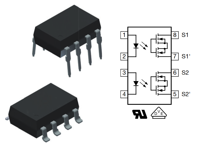
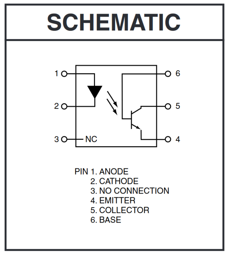
An optocoupler (or optoisolator) is a device that galvanically separates circuits and is not only great at isolation but allows you to interface to circuits with different ground planes or that operate at different voltage levels. Optocouplers are “fail safe” in that if subjected to voltages higher than the maximum rating, they are known to break as an open circuit. An optocoupler achieves this isolation by taking signals that it receives at its input and transferring the signals using light to its output. The optocoupler translates the signal on its input into an infrared light beam using an infrared light emitting diode (LED). The infrared beam crosses a gap inside the optocoupler package to a light-sensitive device (e.g., photodiode, phototransistor, etc.), which changes the light back into a signal again and sends it out of the optocoupler as output. The optocoupler has an air gap or insulating glass inside for the beam to cross, so no electrical connection exists between the input side and output side of the optocoupler. A commonly used optocoupler is the ON Semiconductor 4N25 (formerly Fairchild), as shown in Figure 1.
Optocouplers provide complete electrical isolation between circuits at the input and output terminals of the optocoupler. The optocoupler’s output mirrors the input and connecting an optocoupler is like operating an LED, which may require using a current limiting resistor (check the optocoupler datasheet). Although optocouplers are limited by the frequency at which they can operate (which mainly depends on the type of photoreceptor inside), optocouplers provide protection from overvoltage, high voltage transients, and can be used to eliminate noise outside the optocoupler’s operating range. It seems as if optocouplers would be best used in a digital environment, however, it is possible to use optocouplers to isolate pulse width modulated (PWM) signals. However, the speed of the optocoupler is key; the minimum pulse width of the PWM must be longer than the switching speed of the optocoupler. But how do you tease this information from the optocoupler data sheet?
Put simply, the frequency of the PWM (FPWM) (Hz) is related to the maximum number of steps that the optocoupler must attain. It might be best to just run through some calculations to experiment with the possibilities on paper first, which is more efficient than guessing and buying optocouplers to see if they work.
A quick calculation can be made if you know the frequency of the PWM (FPWM) and the rise time (tR) and fall time (tF) of the optocoupler: FPWM= 2/n(tR+tF), where n is the number of discrete steps that the optocoupler can accommodate. Solve for n:
n=2/[FPWM(tR+tF)]
and you have the number of steps that the optocoupler should be able to accommodate, based on given rise and fall times in the optocoupler datasheet.
Example 1: the 4N25
The 4N25 lists only turn on and turn off times at 2µs and 10 µs (max). Solving for n, you find that at PWM frequency of 2kHz, the 4N25 optocoupler can see a maximum of 83 steps. Unless you are willing to trade down to a much lower frequency from your PWM, the number of steps the 4N25 optocoupler would be able to resolve would be poor. However, a 4-bit PWM yields 16 steps (24 = 16) and since the 4N25 can attain up to 83 steps, these parameters might work together. But if you want to operate at a higher frequency or resolution, a high-speed optocoupler would be better.
Example 2: the FOD8012A
Let’s look at a higher cost optocoupler like the ON Semi FOD8012A, which has a tR and tF of 13ns combined, with the same 2kHz PWM. Solving for n gives us 7,692 steps. Therefore, this optocoupler can resolve 7,692 steps from a PWM running at 2kHz. If you have a 10-bit PWM, which has 1024 steps (210=1024), this high-speed optocoupler would be overkill since the optocoupler can handle over 7,000 steps at that PWM frequency of 2kHz. The point is that the next step is to find a lower cost optocoupler and re-calculate until you find one at the lowest cost and is yet still well above your PWM resolution at your particular frequency. (I have always felt that “price” is a “spec,” but manufacturers don’t like to think like that.) Alternatively, you can see that if you up the PWM frequency to 20kHz, you get 769 steps from the Fairchild FOD8012A. After several iterations of calculations, you start to get a feel for what might work.
Keep in mind that optocouplers vary widely in many respects, including in how devices are characterized from manufacturer to manufacturer. The above is a thumbnail sketch on how to narrow down choices before testing the optocoupler in your circuit.
Applications
Optocouplers are used in power supply regulators, as protection for inputs to microprocessors and other sensitive devices, and in many more applications. Optocouplers are also integrated into other devices such as switches and relays (and marketed as isolated switches and isolated relays) for use in metering, instrumentation, industrial controls, and test equipment.