In the engineering context, the phrase “channel diversity” refers to various techniques for getting a signal from point A to point B. The different approaches to diversity can be used individually or in combination.
Q: What are the primary types of channel diversity in use?
A: There are two primary types: space (spatial), and frequency. Each has different attributes in a given scenario, and product and system costs as well.
Q: Why is diversity needed?
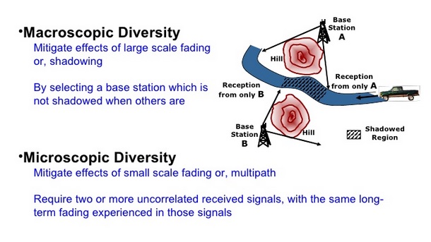
A: In the real world of RF propagation – which is inherently an analog world regardless of whether the signal represents information in analog or digital form – there are many factors which will degrade the signal and the signal-to-noise ratio (SNR), noise and interference, fading due to motion or atmospheric conditions, or an RF shadow created by a structure or hill, among others. These factors can be static or slowly changing, while at other times, they can be fast-changing, Figure 1. They can also be highly localized due to obstacles and shadowing, or “global” due to atmospheric conditions. There are many types of fading and associated fading characteristics, which researchers have classified using statistical and probabilistic techniques, such as linear, exponential, Gaussian, and Rician, among others.
Q: What is space diversity?
A: Space diversity means using different physical paths for the signal, at a single frequency. If these are wireless (RF) paths, multiple antennas are located usually at least between one-half and several wavelengths apart, at the source (transmitter diversity) or receiving points (receiver diversity), or both. Doing so may allow the link to overcome propagation or interference issues. The primary objective is improving system reliability and the ability to “get through.” A secondary consequence is that it may allow supporting a larger number of distinct users, and increasing system capacity.
Q: If space diversity improves the situation, why isn’t it used all the time?
A: Space diversity for RF has a cost in antennas and circuitry, even though an effective way to improve system performance. In the most-common diversity set-up, multiple receiver antennas are used, and the receiver selects the one with the strongest signal strength at a given instant. Space diversity topologies are called SIMO (single input, multiple output), MISO (multiple input, single output), and MIMO (multiple input, multiple output) systems), Figure 2. (Perhaps counterintuitively, the industry uses “input” to refer to the system input to its transmitter function, while “output” refers to the output of its receiver front end.)
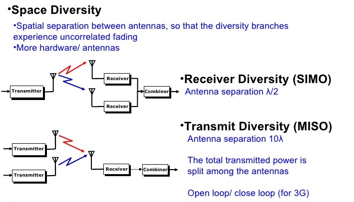
Q: Is space diversity all about improving system performance?
A: Primarily, it is. However, by using widely separated antennas, it also allows multiple independent users operating at the same frequency to share the band. This is because one transmitted signal will be much stronger at one antenna location than at the others, within some limits, and allow some selection.
Q: Are there other ways that space diversity and multiple antennas are used?
A: In modern diversity systems, the multiple antennas can be steered via phase shifting to electronically focus the transmitted signal towards a desired receiver antenna, or the receiver can be focused on a desired source antenna. Other users at the same frequency in the area can have their own focus paths, while minimizing interference between the signals.
Q: Is this sort of diversity in growing use?
A: Yes, absolutely. The 5G wireless standard now being developed on relies heavily on MIMO to maximize the number of users in a given area yet on the same channel. 5G (and other systems) also use MIMO to allow the receiver to select the best-received signal from the multiple versions of the transmitted signal being received, due to multipath reflections, RF barriers, and other path distortions.
Q: Is space diversity limited to wireless RF links?
A: No, space diversity is also used for wired (copper or fiber) links. In these cases, it allows multiple data paths between two points A and B. Thus, it provides redundancy, since there are multiple physical paths between the points.
Q: Is there a relationship between space diversity and the Internet?
A: Yes, although not obvious at first. When the Internet was first conceived as ARPANET, the intention was to build a system which could deliver messages despite impediment due to conflict, natural disaster. For that reason, the message was broken up into short, numbered packets. Each data packet could then travel via a separate route, and then the entire message could be “reassembled” at the receiver. If a packet did not get through, the receiver would send a negative acknowledge (NAK) to the signal source, via any available path, and that packet would be sent again. The individual packets of a given message did not have to travel the same physical route: packet #1 could go via one path, packet #2 by another, and so on. In this way, space diversity enabled a high level of confidence that the entire message would eventually be received.
Part 2 of this FAQ looks at another form of signal-channel diversity to resist the effects of fading and noise: frequency diversity.