It is not uncommon to need a sine wave but how do you generate it? The “best” or most appropriate method for a particular application depends on several things such as:
- frequency,
- purity required,
- amplitude,
- possible synchronization with another frequency,
- variable frequency and/or amplitude.
At lower frequencies a Wien bridge might be considered – for frequencies of up to maybe 1MHz (although in theory it could be used considerably higher in frequency). One disadvantage is it is not easily tunable because the frequency depends on more than one component. Also Wien bridge oscillators need an amplitude stabilization method. This is often a JFET but could be diode based, or even using a small incandescent lamp (not my preferred approach!) or thermistor.
Other options are LC or crystal oscillators which have their place in the designer’s tool kit. If you need to generate a sine wave which is based on a given clock then a different approach is required. A typical situation would be where you need a sine wave based on a precision frequency generated by a microcontroller, CPLD or FPGA. In that case you would presumably have a square wave and need to generate your sine wave from that. If you could make your square wave frequency higher than the desired sine wave then you could digitally generate a sine wave using a sine lookup table. That is the principle used in some DDS (Direct Digital Synthesis) chips – using a DAC (Digital to Analog Converter) and generating the analog values of the sine wave in your digital device. You would also need some analog filtering to remove the higher frequency components of the resulting stepped waveform.
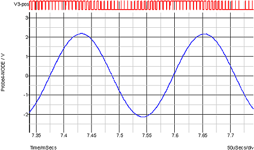
You don’t even need to use a DAC – you could use sine PWM (Pulse Width Modulation). Here you would generate a square wave at a multiple of the desired sine wave and vary the width – not linearly but in a sinusoidal fashion. Then simply filter the output to end up with a sine wave. The waveform below shows the sine PWM signal (top – red) and the filtered result. In this case the PWM frequency is a little under 40 times the desired sine wave frequency.
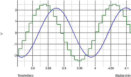
Doing the same thing with a DAC produces a similar result but with the pre-filtered output looking a little different:
Another method is simply to filter a square wave. In that case you will generate a waveform at the same frequency as the square wave rather than a lower frequency. The trade off then comes from how much filtering you need to do to achieve the signal purity you require. The DAC and sine PWM approach can have very simple filtering as the unwanted harmonics are many times the sine frequency. A two pole filter will give very good results and even a single pole filter can be used if the PWM frequency is high enough. The filter would be chosen to attenuate the PWM/DAC frequency while not affecting the sine frequency, but this does not preclude having a variable frequency. Reducing the frequency would involve changing the PWM data but still sending it to the filter at the same frequency. In this was the filtering can stay the same even with a variable frequency.
Variants of these techniques are used in power inverters – using multi-level inverters or a combination of multi-level inversion with sine PWM. Those techniques involve switching power to a positive and negative voltage, zero volts and two or more voltages in between. This creates a very crude DAC based signal but with only 5 levels (or 7 or more depending on how many levels are used). The “DAC” in this case is actually high power and driving an inverter transformer. Adding the “sine PWM” to the technique can smooth out the large steps which result from such coarse steps.
Using a square wave at the same frequency as the desired sine wave requires high suppression of the third harmonic without affecting the fundamental signal. A 4 pole Chebyshev filter is probably the minimum in order to obtain a good sine purity. Having a variable frequency is then tricky.
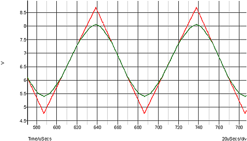
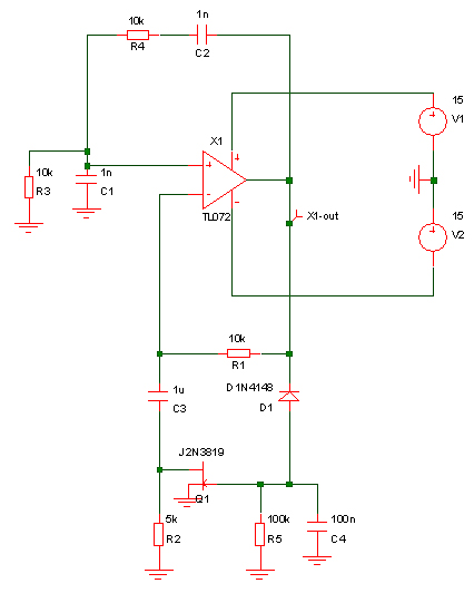
Another technique which is not commonly used in discrete circuitry, but can make sense in an analog custom IC is to shape a triangle wave. A triangle is easy to generate simply by charging and discharging a capacitor with a constant current. It also isn’t too far from a sine wave with only 12% distortion. Rather than simply filtering the triangle, it can be “shaped”. This is something illustrated by the late Hans Camenzind in his “Designing Analog Chips” book. The principle is simply round off the peaks of the triangle so it looks more sinusoidal. His proposed circuitry is shown below:
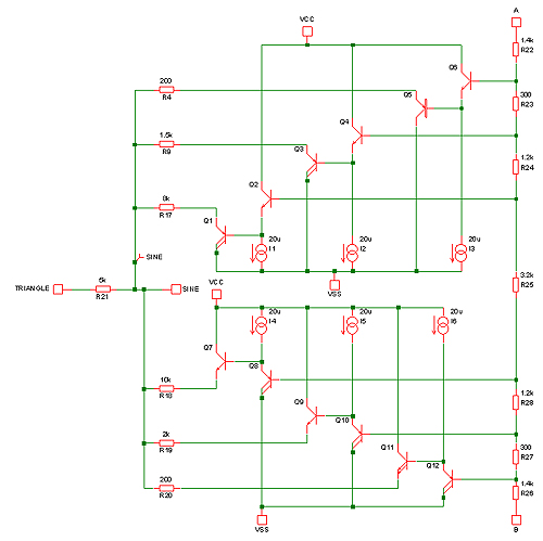
and the results: