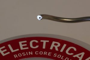
The traditional, older type of solder is a mixture of lead (Pb) and tin (Sn). This type of (60/40 – Pb/Sn) solder melts at 200°C and is typically made up of 60 percent tin and 40 percent lead. However, lead-free solder is desirable today, in terms of avoiding a toxic environment. Lead-free solder is a more modern alloy and still contains tin but replaces lead with non-toxic metals such as copper and silver. The typical lead-free solder melts at 220°C. Lead is poisonous if swallowed, aspirated, or absorbed through the skin. Lead can eventually cause brain damage or death, so use a fan to ventilate your work area and wash your hands after handling lead-based solder.

A decent soldering iron with temperature control is necessary. Make sure that the iron you select has easily replaceable tips. If you’re new to soldering, a heatproof silicone cable is recommended, so it won’t melt if it touches the hot iron. Also, you’ll want to have a soldering stand, a damp sponge to clean the iron tip, and solder. Solder braid will wick excess solder away if there’s a mistake, and for “large solder spills,” there’s a hand tool called a vacuum desoldering pump or “solder sucker” that suctions excess solder away.
Novices to soldering may also want to use a heat sink tool, as heat caused by the soldering process can damage some components. Heat sinks alleviate some of the issues caused by excess heat, preventing the temperature from increasing too much on components such as reed switches, transistors, and integrated chips (ICs). Even a simple alligator clip is preferable to nothing, as it is easy on the wallet and dissipates heat so you can apply heat longer as you solder and avoid damaging your components. To use the clip, attach it to the lead that’s in between the component body and the intended solder joint.
Inside the solder, for electronics, you may find a small core of flux which improves solder flow but is also corrosive. Flux is also a chemical cleansing agent.[1] As solder melts, it cleans metal surfaces. Solder can flow properly onto a clean metal surface (i.e., it’s not oxidized). If oxidization is a problem, before soldering you can take fine-grained sandpaper and gently rub off any oxidized material so that connections made with solder are secure. Oxidized coatings occur naturally and can create a barrier between the solder and the leads or wires, which can interfere with the flow of electrons, acting as an insulator. Solder is available for more than electronics, however. Plumbers use it to “sweat” pipes and fixtures together, and stained glass uses lead came between pieces of glass whose joints need to be soldered to hold the panes of glass together. Solder for plumbing or stained glass should not be used for electronics.

Regardless of what you are soldering (plumbing, stained glass, or electronics), don’t set a soldering iron down on anything other than a soldering iron stand. It’s ok to make a homemade stand that props the tip up away from surfaces, but soldering irons can cause severe burns, fires, and toxic fumes from combustible materials.
Preparation
A sponge can be used to clean the tip of your iron. Wet the sponge on your soldering stand and squeeze out the excess water, as it needs to be damp, not soaking wet. If your stand does not have a sponge, an ordinary sponge from a grocery store is fine. Don’t buy a sponge that’s impregnated with detergents. Don’t get a “magic eraser” type sponge with a fine-pore surface. You want a bit of friction to wipe off the bit of debris that gets created when soldering. Natural sponges are acceptable but unnecessarily expensive and not shaped that well for wiping soldering iron tips. No place to put the sponge? You can wet a cheap sponge, fold it in half, and put it in a tuna or cat food can with the edges pointing up. The solder tip will clean well on those edges.
Place your soldering iron on the stand and wait from 30 seconds to a few minutes (depending on your iron) for it to reach 400°C. Your soldering iron is hot enough when some solder quickly melts on the tip, which you should do anyway before starting. Once the solder begins to melt, tinning the tip lightly with solder assists with good heat transfer when you start soldering.
Soldering components in order
Start with some organization first by laying out all of your components and labeling them. Organizing can make the process less stressful. Many components are through-hole, which means that you will fit the legs of the components through the hole on the PCB.
Before you start soldering ICs or other components that are also sensitive to static electricity discharge, make sure to ground yourself and wear a grounded wrist strap meant for eliminating static discharge build up. It’s like wearing a safety belt; no one wants to do it, but it should be a habit for safety’s sake. Most ICs never demonstrate damage caused by static discharge immediately afterward. However, ICs can certainly degrade in performance much faster if they get zapped by a socks-wearing, carpet-sliding PCB stuffer. If you must solder an IC without a wrist strap, at least ground yourself before handling the ICs. (The enormity of what static discharge can do to chips is much like what germs can do to people. You can’t see it, but it can wreak havoc.)
When you solder components onto a PCB, it helps to start by soldering in the components that are the least affected by heat build-up. Start by soldering IC sockets first (without adding the chip into the socket yet). Next, solder resistors. Capacitors would be next, starting with any caps under 1µF. Next, solder in any caps at or above 1µF, which are most likely to be electrolytic caps (which look a lot like a tiny tin can).
Then solder diodes, LEDs, followed by transistors. Transistors are more liable to get damaged by excess heat, so to be cautious, clip your heat sink (alligator clip) on the transistor leg near, but not touching the can, if possible. Next, add wires, jumpers, and any other components. The board could be cluttered by now, but you’ll want to place your ICs last. Set the IC in place, then firmly and evenly press down on it. Note that some ICs will be in antistatic packaging due to static sensitivity and that you should leave them in the packaging until needed.
In the act of soldering
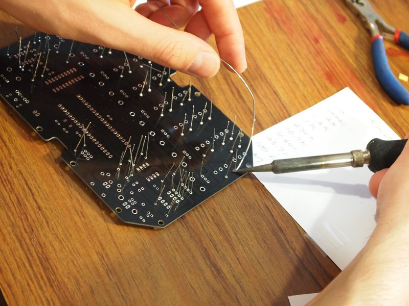
Hold your soldering iron at the base of the handle like you would with a pencil, as to not burn yourself with the tip. The soldering iron should make contact with the leg, or lead, of a component and the trace on the PCB. Next, hold the iron tip on the desired junction/joint for a couple of seconds and feed a bit of solder onto the solder tip where it’s touching the joint. The solder should melt and flow smoothly. Only use enough solder to form a tiny volcano-shaped joint. Next, remove the solder and iron, while keeping the newly joined components still for a few seconds while the joint hardens. The joint should be cone shaped and shiny. If not, reheat and feed in more solder or desolder and try again.
Desoldering
Unless you are a well-tested robot, you’ll need to remove the solder (desolder) a joint at some point along the way. Whether it’s to reposition, remove, or add a component, there are two ways to get the job done.
The first method is to use a desoldering pump with an electrostatic discharge (ESD) nozzle. An ESD protects the ICs that can be compromised by static electricity. To begin, you’d push the spring-loaded plunger down until it locks, setting up the pump. Next, apply the iron tip and the nozzle to the joint and wait a few seconds for the solder to melt. To release the plunger and suck up the molten solder, just press the button on the desoldering pump. Remove as much solder as possible and repeat as needed. Lastly, make sure to empty the pump every once in a while by unscrewing the nozzle and shaking the little misshapen balls of solder into the trash. (Never, ever let children or pets eat the pretty, shiny little solder balls.)
Another way to desolder a joint is to apply a solder braid or wick. A solder braid remover operates like a wick for the molten solder; it flows away from the joint onto the braid.
First, apply the iron tip and the end of the copper braid to the joint. Then, when the solder begins to melt, it will flow away from the joint onto the braid. Then just remove the braid and then the soldering. (If the braid is last, solder can quickly harden and stick the entire braid to the joint you’re trying to clean.) Cut off and throw away the solder-covered part of the braid.
In most cases, you should be able to remove the wire or component easily after it cools down. If not, apply your soldering iron again to melt any lingering solder while gently pulling on the component to free it. (Take care not to burn yourself.)
Chips are no longer large for easy soldering
Sadly, the large PDIP chips that were common a decade or two ago are now very difficult to find. Many manufacturers do not make their chips in PDIP packaging at all now since most soldering is done by machines to stuff PCBs in high volumes. Any company that’s still making a chip in a package that’s large enough to be easily hand-soldered is a saint. No one makes any money on large packages, as most electronics are meant to be as small as possible to save money, especially in high-volume runs. Nevertheless, it’s not just hobbyists that need to make prototypes; every product starts with a dozen or so prototypes that are used for testing and tweaking in real-life before launching high-volume production runs.
Note: This article covers the more important items on through-hole soldering in a nutshell. However, there are hundreds of tutorials on youtube and many other sites that will demonstrate the art of soldering in videos that can’t be covered in a single article. One of the more difficult soldering tasks is soldering extremely small devices with tiny legs/leads/pins that are very close together and sit on the surface of the PCB rather than through holes in the PCB, such as Surface Mount Devices (SMDs).
[1]https://en.wikipedia.org/wiki/Flux_(metallurgy)


