The operation amplifier – commonly called the op amp – is the key building block of analog circuits. In its basic configuration, it is most often used to amplify a signal, of course. It can also be configured to perform mathematical operations such as implementing multiplication or division of two signals, take a square root, or produce the root mean square (rms) value of the input (and note that it is still often the quickest, lowest power, most cost-effective way to perform some of those mathematical operations in real time).
A basic op amp in its most-common configuration as an inverting amplifier requires just a few resistors Figure 1:

While most op amps are used to “gain up” a signal or perhaps attenuate one precisely, there are many specialized op amp variations and topologies which address unique application needs. Among these:
The Buffer Amplifier: this op amp is designed not to amplify the signal but to allow a source with little of its own current-source/sink capability to drive a variety of loads including “heavy” or large loads (meaning they are low impedance, large capacitance, or highly inductive). It is often configured for unity-gain operation (gain of 1). The objective of a buffer amp is that the source circuit or function not be affected or burdened by the inherent characteristics of the load circuit or any changes to the load which may occur.
The Difference Amplifier (also called a diff amp): this amplifier uses a combination of an inverting and non-inverting op amp and, as its name implies, amplifies the difference between its two input voltages while cancelling any voltage which common to the two inputs, Figure 2. The output is ideally proportional to the difference between the two voltages, and is often set to a gain of +1.

In reality, the diff amp is not perfect and the common voltage between the two inputs is not totally rejected. The critical specifications for the diff amp are the common mode rejection ration (CMRR) which defines, in dB, how well the diff amp suppresses this common voltage, and the maximum common-mode voltage (CMV) which the amplifier can tolerate. CMRRs of 80 to 100 dB at 60 Hz (a ubiquitous source of common-mode noise and interface) and maximum CMVs to 100 V are available as ICs.
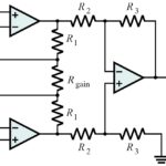
The Instrumentation Amplifier (also called an in amp): This configuration provides two important features, useful for when interfacing with high-precision, high-impedance sensors. It presents a high impedance to the source, and its gain is adjustable by changing the value of a single resistor. It builds on the diff amp and is constructed from a trio of op amps configured as a buffered differential amplifier stage with three new resistors linking the two buffer circuits together but is usually available as a single monolithic device, Figure 3.

These devices are designed so that they provide very low DC offset, low drift, low noise, very high open-loop gain, and very high common-mode rejection ratio. The bandwidth of the in amp is usually relatively low, but that is acceptable for the class of sensors with which it is used.
Now let’s look at other specialty amplifiers including the isolation, transimpedance, voltage/current, and variable-gain amplifiers.
The Isolation Amplifier (also called an iso amp): There is often a need to measure a small voltage which is “riding” on top of a much larger one, and a diff amp does not have the range or CMRR, or the large voltage is potentially dangerous (such as from a single battery at the top of a series sting of dozens or even hundreds of batteries). The isolation amplifier has the unique attribute that there is no galvanic (ohmic) path between its input and its output so the common mode voltage is excluded, and any high voltage on the input will not be seen (literally) at the output, Figure 1.

To achieve this physical isolation between input and output while allowing the signal of interest to pass, the iso amp can use a one of several techniques: magnetic, capacitive, optical, or even RF (wireless). With appropriate design, these amplifiers can provide isolation into the thousands of volts while deftly handling signals down to the microvolt and millivolt range. Note that an iso amp needs two independent power supplies which must be isolated from each other; otherwise, the isolation function is negated.
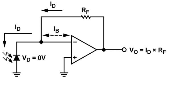
The Transimpedance Amplifier (or trans-Z amp): this configuration accepts a current as its input and transforms it into a voltage, so it can be more conveniently used by the rest of the system, Figure 2. While current outputs from transducers are not as well known as voltage outputs, they are actually very common. Sensors such as photodiodes produce current, not voltage, and need to see a current-compatible amplifier input; also, many industrial sensor or control loops use a 4-20 mA current for the long wire run, to minimize noise pickup (a consequence of the current loop’s inherently low impedance). The transimpedance amplifier’s gain is typically specified in volts output per milliamp input.
The Voltage/Current Amplifier (or V/I amp): this is the complement of the transimpedance amplifier. It takes a voltage as input and transforms it into a current output. Although most circuit designs internally use voltages to represent signals of interest, there are many cases when a current output is needed, such as for producing the 4-20 mA current of the industrial signal loop.
The Variable Gain Amplifier (or VGA): this is an op amp designed so its gain can be changed while it is in the circuit. There are four ways this can be done, depending on the VGA design: via hard-wired jumpers, external resistors, an analog control voltage for continuous gain setting, or a digital control word for discrete gain control.
For hard-wired jumpers or external resistors, the gain value is set once and fixed, and so is difficult to change without reworking the circuitry board. This fixed-gain configuration is useful when a single, standardized front-end circuit design and PC board is to be used across a variety of applications, but with each needing different gain value. In contrast, setting the gain using an analog voltage or digital control allows for more flexibility across multiple products, and extends performance of a single design. It enables the gain to be changed dynamically during operation by the system itself, which is a useful feature and which often eases the overall system-performance challenge.