The mechanical strain induced on electronic components due to mechanical and thermal stress is an important aspect of their performance consistency and limitations; stress is also used to enable some materials to provide critical electronic functions.
Part 1 of this FAQ looked at the basic principles and tests for material strain when stress is applied. Part 2 looks at the implications of these properties for some standard electronic components and functions
Q: How is mechanical strain an issue for electronics, which is usually focused on attributes such as voltage, current, power, and similar attributes?
A: Stress and strain, whether due to directly applied mechanical force or as the result of thermal expansion/contraction, is a factor that affects the data-sheet specifications and performance of almost all components. It is also used to create some components which are essential to modern systems.
Q: In addition to changes in parameters values and performance, what is the effect of stress in some cases?
A: Thermal cycling causes repeated expansion and contraction which, in turn, may cause fatigue and cracking of the physical connection. There are many documented cases of a soldered or mechanical joint failing due to this cycling-induced fatigue (fatigue cracks in aircraft were the subject of “No Highway in the Sky, ”a dramatic 1951 movie with James Stewart and Marlene Dietrich).
Q: What are some examples?
A: Let’s look at two components – a high-precision resistor, and a voltage-reference IC – and the broader issue of the piezoelectric effect.
Q: How is a resistor affected by stress and strain? After all, it’s a passive component.
A: Resistors are stressed in two ways. First, there is temperature change affecting the constituent materials, which can be an increase due to self-heating dissipation, as well as heating or cooling changes in ambient. Second, there is the mechanical stress of their mounting, whether it is to a PC board or something else.
Q: If I use a resistor which is rated for a much higher wattage than it is dissipating, will I eliminate thermal stress?
A: To a large extent, yes.
Q: What about mounting?
A: The basic attachment of a standard SMT-package or a leaded-package resistor to a PC board will induce mechanical stress due to board flex in normal use, temperature changes due to soldering, or temperature changes of the board in its environment. These are not significant in many general applications but may be critical in a high-precision instrumentation application, or if the nominal component value is already close to some performance threshold.
Q: What about higher-wattage resistors?
A: Higher-dissipation resistors can tolerate and survive their heat but are subject to thermal-induced stress. Not only does heat (or cold) affect the electrochemical properties of their materials, but the thermal expansion/contraction of their dimensions affects resistance. Also, any flexing due to vibration will affect these dimensions.
Q: What is the typical range of temperature coefficient of resistance (tempco)?
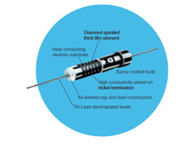
A: A standard “garden variety” resistor has a tempco of about ±500⁰C to ±1000 ppm/⁰C. In contrast, higher-performance components such as those in the CGX series of precision, high-voltage, thick-film resistors from TT Electronics (often used for current sensing), have a modest initial tolerance of 1%, 2%, or 5% and a tempco of just ±50 ppm or ±100 ppm, depending on the version. Resistors such as these are made of specialized (often proprietary) materials which have been selected for low thermal shifts, and the physical construction is also designed to minimize thermal changes (Figure 1). (Note that this resistor is rated for only ½ W, so self-heating is most likely not a significant issue but is still a factor to consider). Resistors with even lower tempco are available but at a much higher price.
Q: What about higher-wattage resistors?
A: Higher-wattage resistors with larger structures often have special mechanical arrangements for attaching a heat sink to the top side or using the PC board as a heat sink, but tight thermal attachment arrangement constraints expansion and thus causes strain, while on/off use may induce thermal cycling and fatigue failure. For that reason, some applications do not turn off their power to allow the component to stabilize at a known temperature and to avoid thermal cycling.
Q: How are active components affected?
A: A voltage reference is a fundamental block of almost any system. Some applications need only modest accuracy and stability for this function, which can be implemented as a discrete IC or embedded within the A/D converter. For highest-accuracy voltage references, discrete standalone reference devices are usually required. The die which contains the reference is stressed in several ways: by the soldering process of the PC board, by thermal shifts even from its slight dissipation, from ambient-temperature changes, and even from flexing of the PC board flexing. Each of these results in minute strains to the die and affects the stability of the reference output.
Q: Can you give an example?
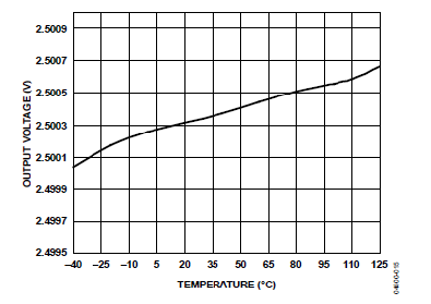
A: For the ADR431 precision voltage reference from Analog Devices with no board- or mounting-related stress on the component, the effect of tempco is shown in Figure 2. While a shift of just a few mV over the -40⁰C to +125⁰C is impressive, there will likely be additional shifts due to the thermally-induced stress at the component-to-board joint and at the die.
Q: What about the piezoelectric effect?
A: The piezoelectric effect is one of the most fascinating electromechanical occurrences. While it is a detriment in some cases, it also offers some of the most-useful characteristics and is employed in many electronic and electromechanical systems?
Q: What is the piezoelectric effect, in brief?
A: It’s a property of crystal materials ranging from natural quartz to engineered ceramics. In short, when the crystal material is physically stressed, the resultant strain in it creates a voltage across the crystal, albeit at a tiny amount of current. In this basic form, it is used for many things, such as a mechanically powered igniter for flammable gases.
But what is also fascinating is that the piezoelectric effect is a symmetrical phenomenon: when a voltage is applied to a crystal, it causes the crystal material to stretch a tiny but consistent amount.
Q: For what is that aspect of the piezoelectric effect used?
A: It’s a long list. In the electrical to mechanical direction, it is used to create sounds (buzzers and basic speakers); and for building tiny yet powerful and precise linear motors and actuators. In the mechanical to electrical direction, it is used for pressure sensors which can tolerate high forces, due to the strength of many crystal materials.
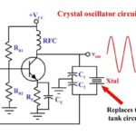
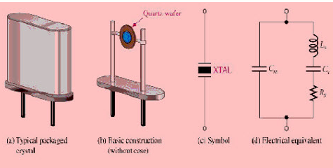
Some applications use both modes. Perhaps the best-known application for the piezoelectric effect is as the heart of a precise oscillator, Figure 3 and Figure 4. The crystal is used to establish and constrain the frequency of a resonant circuit as a resonant AC-excitation wave stimulates it. The crystal not only resonates electromechanically, but it also acts as a narrowband filter and so maintains that desired frequency, based on its mechanical dimensions.

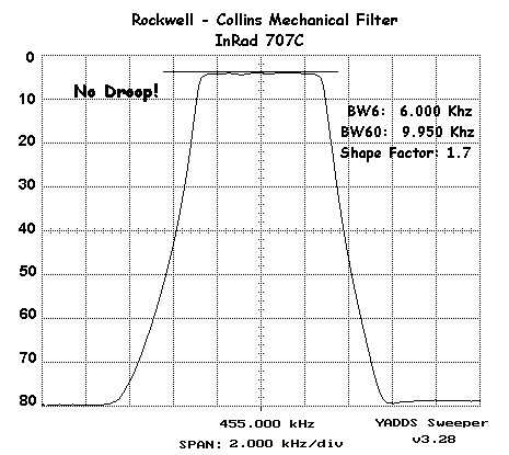
The piezoelectric crystal can also be used just as a filter and is the basis for IF-stage filtering in many AM and FM broadcast-band radios (455-kHz for AM, 10.7 MHz for FM) (Figure 5). These filters provide high out-of-band attenuation, and extremely sharp roll-off without passband ripple – all very desirable characteristics.
Q: Are there other harder-to-see consequences of the piezoelectric effect?
A: Yes, it is an unavoidable, pervasive, ubiquitous phenomenon. For example, there are documented cases of sensitive electronic instrumentation (including oscilloscopes) “seeing” noise spikes which turn out to be due to imperceptible ambient vibration stimulating the piezoelectric effect in ceramic capacitors in the instrument rather than external noise, EMI, or thermal (Johnson) noise.
This FAQ has looked at how material stress, induced by mechanical means as well as thermal changes, can affect and be affected by the performance of electronic components and systems. It is an issue which is inescapable and often plays a larger factor in system performance than initially expected, as well as being the principle behind many widely used components.
References
The topics of stress, strain, materials science, Young’s modulus, the piezoelectric effect, the Wheatstone bridge, crystal oscillators and filters, and related topics are covered in thousands of online and printed sources. These range from general and less technical to highly technical analyses. Among the EE World references are:
- Filters, Part 2: SAW and BAW devices for RF
- Heat sinks, Part 1: Thermal principles
- Heat sinks, Part 2: Available components
- Wheatstone bridge, Part 1: Principles and basic applications
- Wheatstone bridge, Part 2: Additional considerations
- Quartz crystals and oscillators, Part 1: Crystal basics
- Quartz crystals and oscillators, Part 2: Advanced crystals
- FAQ: Piezoelectric motors, Part 1: actuators
- FAQ: Piezoelectric motors, Part 2: drive circuits
- Solid-state temperature sensing Part 1 — principles
- Solid-state temperature sensing, Part 2 – application

