Frequency synthesizers of various architectures, made possible by IC technology, are a key building blocks for applications which must accurately tune multiple channels, and hop from one frequency to another while using a single signal source such as a crystal oscillator.
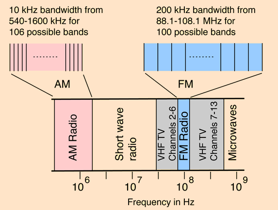
When you want to tune a desired radio station — AM or FM — (Figure 1), or your smartphone, or Wi-Fi links needs to go to a specified frequency as it hops among available channels, or a long-distance wireless link needs to find the signals from a satellite in a spacecraft on its way to Mars, it’s now a simple matter. You just punch in the desired carrier frequency or number – either manually or under the control of a processor – and the RF link is at the desired carrier frequency.
But it wasn’t always so easy. This FAQ will explore digitally synthesized tuning makes this both possible and seemingly simple.
Q: Start with the obvious: what do you mean by “synthesized” tuning?
A: It means that all carrier frequencies to be tuned, whether for transmit or receive, are generated from a single master frequency source.
Q: Do you really generate the carrier frequency itself?
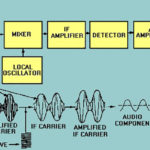
A: In some cases, yes, as with zero-IF or direct-to-baseband topologies, or test equipment. But the majority of RF links use a local oscillator and the superheterodyne architecture. In these cases, the synthesized frequency is offset from the desired carrier frequency by a fixed amount and functions as a local oscillator (LO). The desired carrier and LO are mixed in a nonlinear circuit, and a difference frequency is generated at a fixed frequency called the IF or intermediate frequency (IF). These superheterodyne receiver architectures are discussed in References 1 and 2. Either way, you need a precise, settable sine wave at the desired frequency.
Q: I assume synthesized tuning is a relatively new development…how was tuning down before its development?
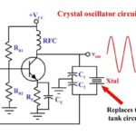
A: In the early days of radio and wireless, tuning was accomplished by adjusting the values of either the inductance or capacitance of an LC resonant circuit (often called a “tank circuit”) to the desired frequency, (Figure 1). While this is effective in theory, in practice it is very challenging, as there are issues of getting to the exact frequency desired, ability to repeat a setting, component aging and drift (in use and even not in use), and overall “coarseness” in tuning precision.
Q: What happened next?
A: The next step was to replace the resonant LC tank with a crystal-based oscillator, using a variety of oscillator circuits (see References 3 and 4). The advantage of the crystal approach is that tuning is as accurate and stable as the crystal itself; these crystals and their oscillators are available as lower-cost, modestly accurate components to ultra-accurate and stable ones in temperature-controlled ovens. But there’s a negative: a given crystal in a basic analog oscillator can operate at only one frequency, and a different crystal needs to be installed for other frequencies.
Q: To what extent is this a problem?
A: Very few wireless (or wired) systems use just a single frequency. They may need to tune to different channels to avoid interference with other users, carry multiple parallel streams of data in parallel, or change frequencies due to changes in propagation circumstances, or to receive different channels. It would be like a TV receiver which could only show a single station unless you physically changed crystals.
Q: This all seems very inconvenient; was this even done?
A: Yes it was. For example, at the height of the Citizen’s Band (CB) radio phenomena in the 1970s, there were 27 channels allocated for these radios in the band, (later increased to 40). Some of the radios had sockets for several pairs of crystals (one for the send channel, one for the complementary receive channel) so the user could switch among those; if other channels were needed, the crystals had to physically swapped. Other radios had sockets for all the channels, so the radio would be loaded with up to 40 ×2 crystals, which was costly and required considerable space. The special knob to switch among all the crystal pairs was also large and costly.
Q: Then what happened?
A: Driven by the need for precise multichannel, crystal-driven channels selection (not just for CB but for TV and many other applications), and advances in digital IC processes, engineers designed ICs for a long-known principle of direct digital synthesis (DDS). It’s a complicated scheme, but if it can be done, it allows for precise, digitally-set tuning in pre-defined steps within a designated band. As such, it is ideal for tuning, signal generation, and countless other situations. First-order accuracy and basic performance are determined by the accuracy and stability of the single crystal.
Q: What is the principle of DDS?
A: There are two related DDS topologies: basic direct digital synthesis, and an indirect enhancement. On the digital side of basic DDS (Figure 2), there’s a binary address counter, a look-up table in memory which contains the values of a digitized sine wave, and a register which holds the selected output of the look-up table. On the analog side, there’s a digital/analog converter and a low-pass filter.
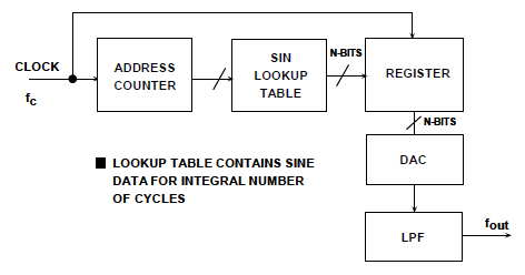
In operation, the system clock increments the address counter which steps through the digitized sine value in the table. These values are then passed through the register to the D/A converter, filtered to remove the step edges, and a smooth sine wave emerges. The frequency of this sine wave is determined by the clock rate.
Q: This doesn’t make sense since you still need a controllable, variable-frequency clock to create sine waves of different frequencies given it doesn’t seem to allow generation of many frequencies from a single crystal acting as a clock source. What’s happening?
A: By setting up the lookup table with different content data and changing which part of the lookup table is read out, it is possible to generate different frequencies. Still, this is often inadequate for the project.
Q: What can be done about this?
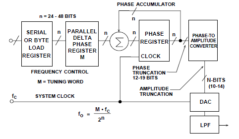
A: An indirect approach can be used, with a numerically controlled oscillator (NCO) (Figure 3). The operation is complicated, but in simplified form, the phase accumulator is directed to point to a specific new address in the lookup table, and so can “jump” to different frequencies. Note that the literature on this subject cites both frequency and phase, as they are intimately related: frequency is the rate of change of phase. Therefore, if you can control where you are in the waveform phase, you can control the frequency as well.
Q: This all seems very complicated; does it work?
A: Yes, it is complicated, and yes, it does work, and work well. Reference 5 gives a more detailed but still simplified explanation.
Part 2 of this FAQ will look at other synthesizer variations as well as performance criteria.
References
- EE World, “Radio receiver architectures, Part 1—TRF and Superhet”
- EE World, “Radio receiver architectures, Part 2—Zero-IF and SDR”
- EE World, “Quartz crystals and oscillators, Part 1: Crystal basics”
- EE World, “Quartz crystals and oscillators, Part 2: Advanced crystals”
- Analog Devices, MT-085 Tutorial, “Fundamentals of Direct Digital Synthesis (DDS)”
- Texas Instruments, Technical Brief SWRA029, “Fractional/Integer-N PLL Basics”
- Floyd M. Gardner, “Phaselock Techniques, Third Edition”