Part 1 of this FAQ provided context and background on the PC board, and discussed its first widespread appearance as a phenolic-based board. Part 2 looks at some board issues and the widely used FR-4 PC board substrate.
Q: I see the term “solder mask” — what is that?
A: Solder mask (also called a solder stop mask or solder resist) is a thin, lacquer-like layer of polymer that is usually applied to the copper traces of a printed circuit board (PCB) for protection against oxidation and to prevent solder bridges from forming between closely spaced solder pads. It is not applied to the places where component leads and PC board traces meet and must be soldered in the soldering wave machine or soldering oven.
Q: How are designations (callouts) such as IC1 or R4 printed onto the PC board?
A: After the solder mask is applied, a silkscreen with the needed designations is printed onto the mask. Green is the most common color for the silkscreen, but other colors are used.
Q: I don’t see many of these phenolic bards, so what happened?
A: They simply could not handle the requirements of electronics circuits and components into the 1980s and 1990 in terms of thermal and mechanical stability, consistency, ability to support narrow traces and tiny holes, and two-sided and multilayer demands. Thus, the glass-epoxy PC board was developed; the most-common version is known as FR-4 (sometimes written FR4
Q: Can you tell me more about FR-4?
A: FR-4 is a general designation for a matrix of fiberglass and epoxy which is used for most of today; s PC board substrates. It is available in various standard thickness, chosen as a function of the size of the board, flexing issues, and rigidity requirements. ). The FR-4 designation is now also a generic term used by many engineers for any fiberglass-epoxy PC board, even if it is not FR-4 in the formal standards sense, as there are many substrates which are similar to FR-4 but do not adhere to the formal specification.
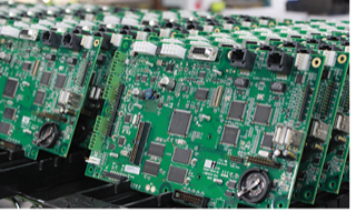
Standard single-weight thickness is 0.031 in (0.78 mm), followed by double- and triple-thicknesses of 0.062 in (1.57 mm) and 0.093 in (2.36 mm), respectively; thinner ones are also available. Reference 1 has a table listing about 30 of the nominal electrical and mechanical characteristics of FR-4; they are vital to consistent performance and the ability to use different sources for raw boards and fabrication. FR-4 usually green in color, but other such as blue are sometimes used. There is no standard PC length or width, nor does the board have to be rectangular; it can be circular and have cutouts or whatever is needed. In many ways, the green PC board is the defining image of modern electronic circuits (Figure 1).
Q: Why is the fire-resistant FR rating needed?
A: The “FR” rating means, among other issues, that the board will not sustain a fire. This was a key factor in allowing use of these PC boards in their earliest days ,when voltages and currents were high and hybrid tube/transistor designs were common; it is needed now as circuit current levels on some boards are in the tens and hundreds of amps, which can initiate a fire if there is a short circuit. (Obviously, a device running on a small battery goes not need this rating.)
Q: What about the cladding?
A: Glass-epoxy boards such as FR-4 can be clad on one side or both sides as needed by the design and layout. With today’s circuit complexity, single-sided is sufficient only for relatively simple designs.
Q: What is the thickness of the copper cladding?
A: The industry standard is called “one ounce” in the US, meaning 1 ounce of copper/ft2 of the board, equivalent to 35 µm thickness. Two- and three-ounce claddings are also in use as well a thinner half-ounce cladding. This thicker copper is needed when the current levels are higher and IR drop along the PC board traces may be excessive, or the self-heating due to I2R dissipation cause excess temperature rise. Convenient online applications are available which allow you to enter the PC board’s trace dimension (width, height, and length) and current to resultant IR voltage drop and I2R temperature rise, see Reference 2.
Q: What are some other FR-4 considerations?
A: The material is mechanically strong, rugged, and stable. As a result, holes cannot be punched; instead, they must be drilled. The glass-epoxy material is very tough on drill bit life, and also on the shears used for trimming or cutting boards. These are factors which make fabrication using FR-4 PC boards more costly than it is with phenolic ones, in addition to raw material cost.
Part 1 of this looked at the background and basics of PC board technology and introduced the ubiquitous FR-4 substrate. Part 2 looks in more detail at FR-4 boards, and what the next phase of PC board technology looks like – and why.
Part 3 looks at advanced PC board issues such as vias and multilayer boards.
References
- Wikipedia, “FR-4”
- PCB trace calculators: MustCalculate, Bittele Electronics Inc. and Trance-Cat
- Wikipedia, “Printed circuit board”
- Wikipedia, “Via (electronics)”
- SEEED Studio, “Printed Circuit Board(PCB) Material Types and Comparison”
- Al Wright, Epec LLC., “PCB Vias – Everything You Need To Know”
- Microwaves101, “FR-4”
- All About Circuits, “Which Via Should I Choose? A Guide to Vias in PCB Design”
- Rogers Corp., “Evaluating PCB Plated Through Holes For 5G Applications”
- John W. Schultz, Compass Technology Group, “A New Dielectric Analyzer for Rapid Measurement of Microwave Substrates up to 6 GHz”
- Rogers Corp., “Characterizing Circuit Materials at mmWave Frequencies”
- Rogers Corp., “Laminate Materials Simultaneously Increase μ and ε, Reducing Antenna Size”
Related EE World Content
- What are RF waveguides? Part 1: context and principles
- What are RF waveguides? Part 2: implementation and components
- Passive microwave components, Part 2: couplers and splitters
- Passive microwave components, Part 1: isolators and circulators
- Next-gen laminates improve insertion loss in automotive radar sensor applications
- High-impedance laminates help reduce antenna size
- Laminates for 5G and other millimeter wave applications

