The microstrip antenna is a convenient, planar, easy-to-fabricate antenna with some attractive attributes and features, as well as some distinct limitations.
The passive antenna is a critical part of any wireless communications link, for both transmit and receive sides. Depending on the application, the same antenna may be used for both roles, or radically different ones may be employed. This FAQ looks at antennas in brief and at a specific antenna embodiment: the microstrip (patch) antenna.
Q: What are the functions and objectives of any antenna?
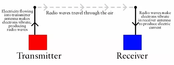
A. An antenna is an energy transducer (Figure 1). A transmitting antenna takes electrical and electronic power (and energy) originating at an amplifier and which is in a confined space such as a wire or a waveguide and disperses (radiates) it as electromagnetic (EM) power into free space. A receiving antenna performs the complementary operation, capturing this EM energy in free space and confining it to a well-defined path (again, a wire or waveguide, as examples), then sending it to an RF front end.
Q: What are some of the key parameters which are used to characterize antennas?
A: As with any electronic component, whether active or passive, there are some top-tier factors which define performance. For antennas, these are:
- Center frequency
- Radiation pattern
- Radiation pattern bandwidth
- Sidelobe level
- Directivity
- Gain
- Efficiency
- Effective area
- Aperture efficiency
- Polarization
- Input impedance
The references explain these in more detail; some are “intuitive,” while others require a deeper understanding of EM physics. One or more of these will be more dominant factors in design and selection than the others. Still, there is no formal ranking of their importance, as the relative ranking is a function of the application and its priorities.
Q: How does an antenna differ from many other passive components?
A: Antennas have tradeoffs (also called “compromises”) as do all components, but they often not so much related to compromise but instead focused on optimizing the antenna’s match to the application. There is no such thing as an “ideal” antenna because every application has its own priorities. For example, some applications need high directivity while others need the omnidirectional capability, Or some want wider bandwidth, and others need only narrower bandwidth. These are not tradeoffs or compromises: they are deliberate choices made to better-fit the antenna to the application needs. With antennas, there are many degrees of freedom to consider; some of these are tightly linked to each other, while others are more loosely linked.
Q: What does a typical antenna look like?
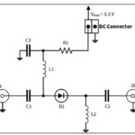
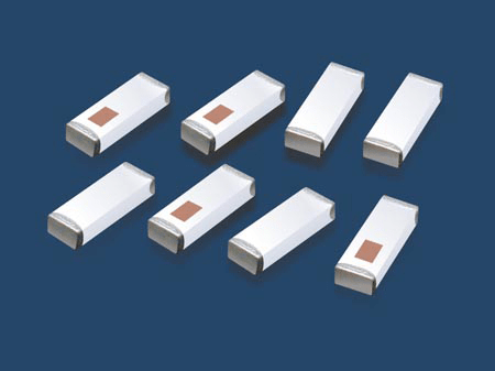
A: That question cannot be answered as there is no such thing as a “typical” antenna. The classic whip or discrete wire antenna of decades ago, and often seen in movies, is just one of many physical antenna types (Figures 2 through 4).

Q: What does the antenna genealogy “family tree” look like?
A: That’s a simple question with a complicated answer, as it depends on the perspective of the person drawing that genealogy tree; Figure 5 is one example. Some classifications are based on the underlying EM physics principles. In contrast, others are derived from the actual physical realization, which is somewhat related to principles but not strictly defined by them.
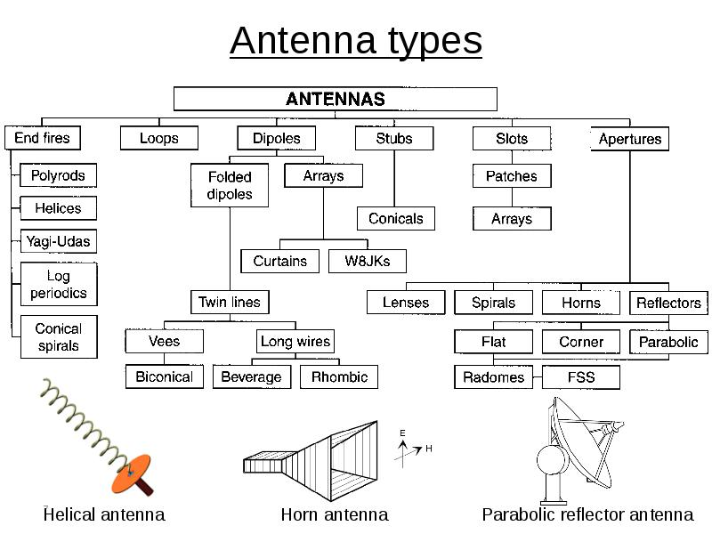
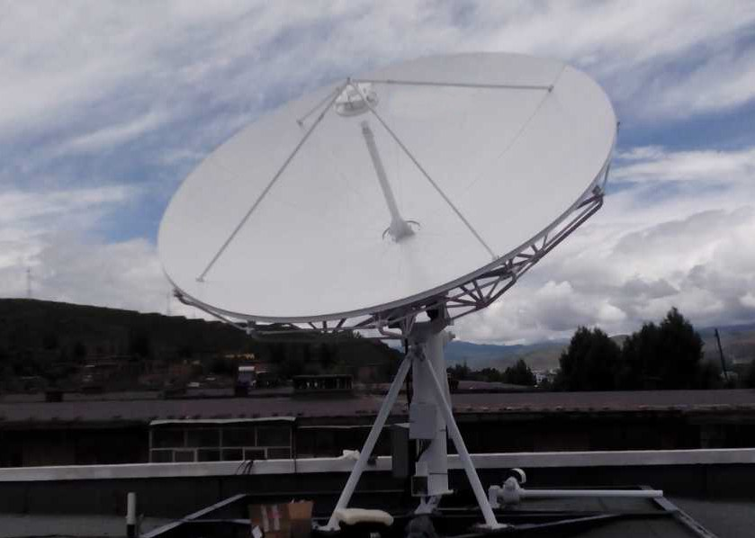
Among the basic antenna groups, the earliest antenna belongs to what is called the “wire” style (although often made of tubing or pipes in reality) such as the long wire, whip, and dipole antennas. Using very different embodiments of the same EM physics principles, there are small resonant antennas used in smartphones. There are also reflective antennas which use a parabolic dish or plane reflector behind the electrically connected main element, horn antennas, and microstrip antennas, to cite just a few basic types.
Q: Is that all?
A: Not at all. Antennas come in countless variations and permutations on their basic styles, and in many cases, are a blend of several types. For example, a parabola dish antenna may have a folded dipole or horn at its focal point. The many antenna physical realizations in use are clear proof of the art and ingenuity of designers as they work to meet specific goals and priorities. (If you need further evidence, take a look at some issues of QST, the flagship publication of the ARRL – the American Radio Relay League).
Q: How are antennas designed?
A: Decades ago, an antenna design started with an idea for the configuration and some basic analysis based on Maxwell’s equations for the sizing of antenna elements, followed by building and testing. In recent years, the design mode has shifted radically to the designer establishing a configuration and then modeling it in detail using an “EM field solver” application. These advanced applications take into account the real-world factors such as fringing and parasitics, which affect antenna dimensions, configuration, and performance, and which were nearly impossible to assess in advance using “rules of thumb” and experience alone.
However, these advanced analysis and modeling applications cannot suggest radically new configurations; in most cases, that is done by leveraging and expanding on existing approaches or the intuition or experience of the designer. These hunches can then be verified and fine-tuned by the EM field-solver software and extended to “what if?” modes and sensitivity analysis.
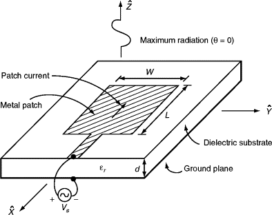
Q: What is a microstrip antenna?
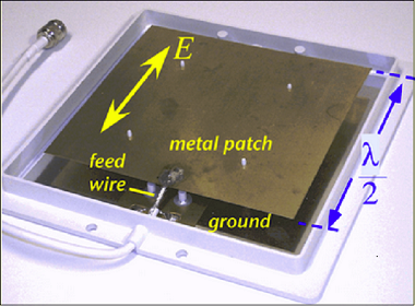
A: A microstrip antenna, also called a patch antenna or printed antenna, is an antenna which is primarily a two-dimensional flat structure (Figure 6. In its simplest form, it uses a conducting “patch” one-half wavelength long, so that the metal surface acts as a resonator similarly to the half-wave dipole antennas.
Q: Is that it, or is there more to the story?
A: Of course there is more! It is often built by simply mounting or fabricating a suitably dimensioned metal sheet or surface on an insulating dielectric substrate, such as a printed circuit board. The opposite side of the PC board substrate is also cladded and so forms a ground plane, or another conductive surface is added ion the other side of the dielectric. As a result, it is easy to design and inexpensive to manufacture. They can be built as standalone, discrete devices as a “sandwich” of conductive material, dielectric, and conductive material as the ground plane.
Microstrip antennas are useful about 500 MHz to as high as 100 GHz; at the lower frequencies, they can be fairly large due to their half-wavelength dimension. As with many simple antennas, the basic EM theory and Maxwell’s equations needed to model them start simple, but fringing, physical reality, tolerances, and parasitics play a large role in their actual performance.
Part 2 of this FAQ will explore the microstrip antenna in more detail, including its primary attributes, advantages and disadvantages, and variations.
EE World Related Content
Take a class in SDR and antenna design
The difference between active and passive antenna systems
Hidden pitfalls of IoT antenna design
New Antenna Concept Developed for Cars
What are RF waveguides? Part 2: implementation and components
What are RF waveguides? Part 1: context and principles
5 things you need to know about 5G filters
Passive microwave components, Part 2: couplers and splitters
Passive microwave components, Part 1: isolators and circulators
How do RFID tags and reader antennas work?
References and Resources
Basics and tutorials
- Maxtena, “Microstrip Patch Antennas”
- IOP Conference Series: Materials Science and Engineering, “Design, simulation and analysis: a microstrip antenna using PU-EFB substrate”
- Pasternack, “Microstrip Patch Antenna Calculator”
- EU Radar Tutorial, “Patch Antenna or Microstrip Antenna”
- Ranga Rodrigo, Arab Academy for Science, Technology, and Maritime Transport, “Fundamental Parameters of Antennas”
- Pongsak University, Thailand, “Chapter 2 : Fundamental parameters of antennas
- Tutorials Point, “Antenna Theory – Micro Strip”
- Universal Engineering College, University of Calicut, “Radiation and Propagation: Fundamentals of Antenna”
- ResearchGate, “An Overview Of Microstrip Antenna”
- ResearchGate, “Design of rectangular microstrip patch antenna”
- ResearchGate, “Methods to Design Microstrip Antennas for Modern Applications”
- Science Direct, “Microstrip Antenna”
- Science Direct, “Stripline”
- Antenna-Theory.com, “Microstrip (Patch) Antennas”
- Antenna-Theory.com,“PIFA – The Planar Inverted-F Antenna”
Advanced microstrip antenna implementations
- Elsevier, Science Direct, “A Novel Compact Dual Frequency Microstrip Antenna”
- Elsevier, Journal of Applied Research and Technology, “Design of triple-layer double U-slot patch antenna for wireless applications”
- ResearchGate, “Methods to Design Microstrip Antennas for Modern Applications”