There are many ways to implement the automatic gain control function, critical to proper performance of many wireless and other links.
The previous section discussed the context and need for AGC. This section will look at the different ways in which the AGC function is implements, and some of the parameters associated with the AGC function.
Q: What are some terms associated with AGC?
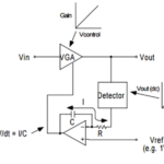
A: AGC is the overall desired function. It is actually implemented via a signal-strength detector which controls a variable gain amplifier (VGA) or voltage-controlled amplifier (VCA); the VCA is the most common implementation of a VGA, and the designations are often used interchangeably.
Q: Is that it? End if discussion?
A: Absolutely not. The next question is how to do you measure the signal strength to control the VCA. There are four viable approaches and the best one to use depends on signal type, frequency, expected dynamic range, and many other factors. In each case, the output of the detector is connected to and controls the VCA. That output is usually a basic signal such as 0-1 V, 0-5 V, 1-5 V or similar.
Q: What are these four approaches?
A: They are the envelope detector, the square-law detector, the true-RMS detector, and the logarithmic (log) detector. The first AGCs used envelope and square-law detection because they were the only ones which were practical to build. Now, ICs which provide true-RMS and log-detection characteristics are widely available and offer better system performance in some applications.
Q: What are the attributes of each of the four types:
A: Here is a brief overview:
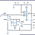
- The envelope detector (also called a peak detector): The output of an envelope detector (usually a half-wave or full-wave diode circuit) is proportional to the absolute magnitude of the instantaneous RF input voltage (Figure 1).
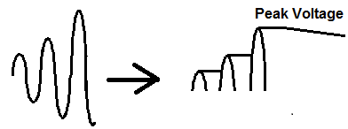
Low-pass filtering will eliminate ripple at twice the RF frequency. It is similar to the basic demodulation circuit of the classic crystal radio, which is a peak detector for the modulated AM envelope. The peak signal output is then scaled and buffered, then used to drive the VCA. The rate at which the peak-voltage value is allowed to droop determines the decay rate for the AGC.
- The square-law detector: This detector has an instantaneous output proportional to the square of the instantaneous RF input voltage, which means that its output is proportional to input power.
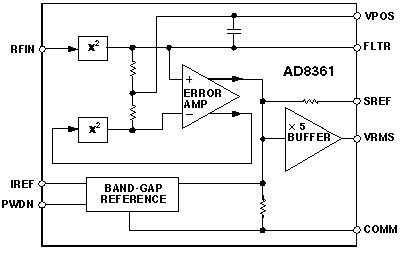
- The true-RMS detector: This detector is a square-law detector followed by a low-pass filter, then followed by a square-root function. The low-pass filter performs the “mean” operation associated with the root-mean-square function. Due to the square-root function in this detector, the average output is proportional to signal voltage, not power. It is relatively easy to build a basic true RMS detector using op amps; now, it is more common to have a single IC which embeds all the needed op amps and associated circuitry (Figure 2).
- The log detector: This type of detector produces a linear output which is proportional to the logarithm of the RF input voltage. The core of the design leverages the exponential voltage/current relationship of a diode, but a useful circuit is actually quite complicated; an IC is the most practical way to accomplish this. Due to the logarithmic nature of the design, the log detector can usually handle a very wide range of input signals, typically 60 to 80 dB or more.
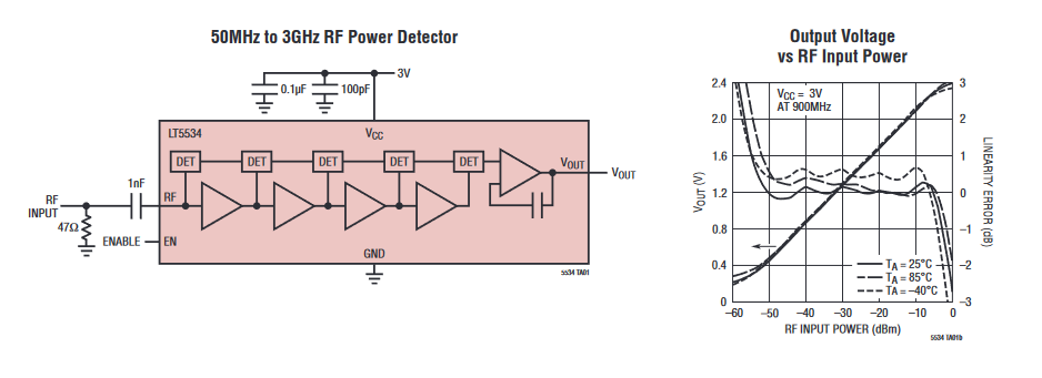
One example is the LT5534, a 50 MHz to 3-GHz monolithic-RF power detector capable of measuring RF signals over a 60-dB dynamic range (Figure 3). The RF signal in a decibel scale is precisely converted into DC voltage on a linear scale. The 60-dB input dynamic range is achieved using cascaded RF detectors and RF limiters. Their outputs are summed to generate an accurate log-linear DC voltage proportional to the input RF signal in dB.
Q: Why so many choices?
A: The detector’s response law (linear, log, square law, etc.) plays an important role in determining the loop’s dynamic response during large, abrupt changes in signal level. This influences the dependence of the loop’s stability or equilibrium level on the input’s waveform or crest factor.
Q: What’s the relationship Between the AGC and signal strength indication with a log detector?
A: The VGA’s gain-control voltage has an accurate logarithmic relationship to the input signal level when the loop is in equilibrium. This means that the gain-control voltage may also be used as an excellent received signal strength indicator (RSSI), which usually a dB function. Non-log control voltages can also be used, but as they are not logarithmic, they soon run out of range and headroom.
Q: What are some AGC detector characteristics that are of concern?
A: There are many, but the top ones include AGC response time and bandwidth. First, the detector itself must have the bandwidth to sense the input signal properly. In other words, if the detector has only 100-kHz bandwidth but the signals being assessed are in the multi-megahertz or gigahertz range, the detector will not be able to provide a suitable and legitimate controlling signal.
Further, AGC loop response time is important. As usual, there is a tradeoff between having the loop respond quickly to input-level fluctuations versus having it modify the actual amplitude modulation on the signal. The way the AGC responds to input-amplitude changes is critical and varies with detector type (Figure 4).

If the loop responds too quickly, the result is undesired gain modulation due to the loop’s attempt to stabilize the output level of a signal containing valid amplitude modulation. Such gain pumping can detrimentally impact signal-chain performance.
Q: What else is of concern in an AGC circuit or IC?
A: As always, performance stability with respect to temperature and even voltage rails may be a concern in a given application. If the performance of the AGC changes with these, system performance may go out of allowed bounds. AGC ICs and circuits are usually designed with various forms of internal compensation to minimize these shifts and provide tightly bounded performance despite these variations.
Q: That sounds like a lot, is there more?
A: Of course, there always is. The AGC performance and attributes must be matched to the expected signal type. For example, an AGC for radar is very different than one for cellular-phone signals and even different for different modulation types (3G, 4G, 5G).
As a result, the AGC function and the components which implement it are critical to system performance and are carefully analyzed for errors or deviations in its input/output transfer function. Further, the data sheets for advanced AGC detectors are complicated, with numerous charts and graphs for their performance under a wide range of conditions, and perspectives. This is especially true as you move up the detector “sophistication” ladder: the data sheet for an envelope/peak detector is not as complex as the lengthy one for a log detector.
Q: Is there a special issue with AGC for AM signals?
A: Yes, AM radio (still used!) is a challenge because amplitude variations are how the modulating signal is encoded. If the AGC responds too quickly, it will have the effect of “stripping out” some of the amplitude variations which represent signal, and so degrade the link performance. Careful setting of AGC response time is needed even in the case of basic amplitude modulation.
Q: What about the technical performance of the VCA/VGA?
A: The VCA/VGA is an inherent part of the gain-control loop and its performance is actor in overall AGC-function performance. The VCA/VGA must provide a consistent, linear transfer function of attenuation versus control voltage over the specified range of both signals. The details are beyond the scope of this article. In some ICs, the VCA/VGA is built in along with the detector; in other cases, they are selected as independent components.
The next part looks at some other AGC applications and uses.
Related EE World content
How does a precision rectifier work?
Digipots as electronic potentiometers, Pt 3: Enhancements
Analog computation, Part 1: What and why
Analog computation, Part 2: When and how
RMS power detector operates up to 30 GHz
Why use a nonlinear amp?
Stanford researchers build earthquake observatory with optical fibers
RF over fiber: overcoming an inherent transmission-line problem, part 1
RF over fiber: overcoming an inherent transmission-line problem, part 2
Free-space optical links, Part 1: Principles
Free-space optical links, Part 2: Technical issues
Free-space optical links, Part 3: Standard units
Undersea optical-fiber cables do double-duty as seismic sensors, Part 1: Context
Undersea optical-fiber cables do double-duty as seismic sensors, Part 2: Application
External References
AGC for wireless and other channels
- All About Circuits, “Understanding Automatic Gain Control”
- Science Direct, “Automatic Gain Control” (shows its use in various non-wireless applications)
- Analog Devices, “Design and Operation of Automatic Gain Control Loops for Receivers in Modern Communications Systems”
- Analog Devices, “AD8368 800 MHz, Linear-in-dB VGA with AGC Detector”
- Analog Devices, CN3090, “20 GHz to 37.5 GHz, RF Automatic Gain Control (AGC) Circuit”
- Analog Devices, “Chapter VIII: Design and Operation of Automatic Gain Control Loops for
Receivers in Modern Communications Systems” - Analog Devices, “Stable, Closed-Loop, Automatic Power Control for RF Applications AN-1507”
- Analog Devices, “Measurement and Control of RF Power (Part I)”
- Analog Devices, “Measurement and Control of RF Power (Part II)”
- Analog Devices, “Measurement and Control of RF Power (Part III)”
- net, “Automatic Gain Control (AGC) in Receivers”
- Electronics Notes, “Superhet Radio AGC – Automatic Gain Control”
- EETimes, “Wireless 101: Automatic Gain Control (AGC)”
AGC in Wein-bridge oscillators
- Worcester Polytechnic Institute, “Wien Bridge Oscillator: Automatic Gain Control (AGC)” (lab project with analysis)
- Wikipedia, “HP 200A” https://en.wikipedia.org/wiki/HP_200A (light bulb as PTC resistor)
- Hewlett-Packard, “Schematic for Success: The HP200A” (schematic with specifics and bulb)
- Hewlett-Packard, “A real gem: HP’s audio oscillator patent turns 60” (HP 200 history)