There are many ways to implement the automatic gain control function, which is critical to proper performance of many wireless and other links.
The previous parts looked at the AGC in the context of its broadest application of wireless links. This part looks at some other aspects of AGCs.
Q: What other applications use AGCs?
A: AGC functionality is used extensively in other situations. Among the applications are hearing aids, where the audio signal can range over many tens of decibels (whisper, normal conversation, loud talking, music). Even seismic-activity data logging uses it to even out the largely unknowable signal intensity.
Q: What are some other situations?
A: AGC is used where a signal must be captured and analyzed with high resolution over a wide range, such as a weigh scale which must provide many bits of resolution (12, 14, 16 bits, or more) for weights ranging from a few grams to, say, 100 kilograms—that’s a 100,000:1 span.
If the gain is fixed at a high level to provide the needed signal amplitude for the grams, the amplifier will saturate at even a few kilograms. Conversely, suppose the gain is set at a reduced value to allow high resolution at tens of kilograms. In that case, the signal level for low weights will be impossible to resolve precisely. To overcome this slow problem, an AGC circuit scales the AFE gain to optically match the scale sensor output to the AFE input range anywhere and with adequate resolution. In such cases, the VCA usually is designed to have preset, discrete-gain step sizes rather than a continuous analog value. The step size and associated gain are then used to calculate the actual weight.
Q: Is there a special AGC situation for ultrasound?
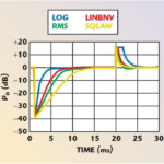
A: Yes, when used in a medical setting. Unlike many RF channels with varying or poorly known attributes, the medical ultrasound situation is this: the attenuation versus distance of ultrasound waves at the frequency in use is known (about 0.5 to 1 dB/cm-MHz in soft tissue), as is the propagation velocity of these waves through human tissue (1.54 mm/µsec). Since the transmitted ultrasound signal decays as it propagates and decays further as it reflects and returns to the receiver, the ultrasound AGC is set up to automatically increase the gain versus time by a corresponding factor. The result is that the return ultrasound signal is maximized, along with SNR, yielding a better, more detailed image.
Q: How do optical-fiber systems use AGC?
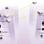
A: Even low-loss optical fibers have losses, which can add up over a fiber link that spans tens of kilometers. Other losses occur when the optical fiber is used in a networked arrangement where optical channels are added or dropped, so optical power shifts up or down.
Q: How is AGC implemented in an optical-fiber system?
A: AGC and automatic power control (APC) are usually used in in-line optical amplifiers to regulate the optical gain and the output signal optical power of an EDFA. Because both the optical gain and the output signal optical power depend on the pump’s power, automatic control can be accomplished by adjusting the pump power. (Keep in mind that for optics and photons, you control power by increasing/decreasing the number of photons; you cannot change the power of individual photons, of course.)
Q: How does this APC work?
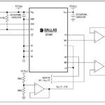
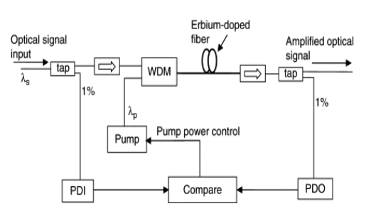
A: In a standard erbium-doped fiber amplifier (EDFA) design with AGC, two photodetectors (here, PDI and PDO) detect the input and the output signal optical powers. The circuit compares the two power levels, calculates the needed optical gain of the EDFA, and generates an error signal to control the injection current of the pump laser if the EDFA gain is different from the target value (Figure 1).
Q: Are there any other ways in which AGC is used?
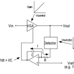
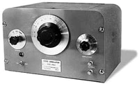
A: Yes, it is used to stabilize circuits such as oscillators by maintaining a constant feedback level. In fact, it was the key to stabilizing the performance of the legendary Hewlett-Packard HP200A oscillator, which was launched by that company in the late 1930s (Figure 2).
Q: How does stabilizing an oscillator relate to AGC for a communications link?
A: It does, and it doesn’t; it’s a matter of semantics. A standard oscillator topology such as the Wein bridge is an “almost” unstable circuit—it oscillates on the verge of going unstable due to positive feedback applied to maintain the oscillation. The challenge is to keep the oscillator on the edge of instability, but normal variations in component values, thermal drift, and other factors will cause it to go out of control.
Q: What was the H-P solution?
A: Based on a suggestion by their mentor Prof. Frederick E. Terman, Bill Hewlett realized that negative feedback could stabilize the circuit, but it, too, had to be regulated to maintain loop stability. He achieved this by inserting an incandescent bulb in the negative feedback loop, which stabilized the oscillator, with the bulb acting as a negative temperature coefficient (NTC) resistor (Figure 3).


As the feedback signal increases, the bulb filament heats up, and its resistance increases, decreasing the signal amplitude; conversely, if the feedback signal decreases, the bulb is cooler, and its resistance also decreases, and thus the signal amplitude is allowed to increase. This is the embodiment of a closed-loop, self-adjusting system and started Hewlett-Packard’s success, as it crisply and simply solved a long-standing problem.
Conclusion
The AGC function is critical to the successful and viable operation of many communication circuits as well as other functions. While AGC seems like a straightforward closed-loop function, it has many subtleties when designers try to achieve the highest levels of system performance. Many innovative approaches and components have been devised to build the necessary detector providing suitable performance, and users must assess the system needs versus available solutions.
Related EE World content
How does a precision rectifier work?
Digipots as electronic potentiometers, Pt 3: Enhancements
Analog computation, Part 1: What and why
Analog computation, Part 2: When and how
RMS power detector operates up to 30 GHz
Why use a nonlinear amp?
Stanford researchers build earthquake observatory with optical fibers
RF over fiber: overcoming an inherent transmission-line problem, part 1
RF over fiber: overcoming an inherent transmission-line problem, part 2
Free-space optical links, Part 1: Principles
Free-space optical links, Part 2: Technical issues
Free-space optical links, Part 3: Standard units
Undersea optical-fiber cables do double-duty as seismic sensors, Part 1: Context
Undersea optical-fiber cables do double-duty as seismic sensors, Part 2: Application
External References
AGC for wireless and other channels
- All About Circuits, “Understanding Automatic Gain Control”
- Science Direct, “Automatic Gain Control” (shows its use in various non-wireless applications)
- Analog Devices, “Design and Operation of Automatic Gain Control Loops for Receivers in Modern Communications Systems”
- Analog Devices, “AD8368 800 MHz, Linear-in-dB VGA with AGC Detector”
- Analog Devices, CN3090, “20 GHz to 37.5 GHz, RF Automatic Gain Control (AGC) Circuit”
- Analog Devices, “Chapter VIII: Design and Operation of Automatic Gain Control Loops for
Receivers in Modern Communications Systems” - Analog Devices, “Stable, Closed-Loop, Automatic Power Control for RF Applications AN-1507”
- Analog Devices, “Measurement and Control of RF Power (Part I)”
- Analog Devices, “Measurement and Control of RF Power (Part II)”
- Analog Devices, “Measurement and Control of RF Power (Part III)”
- net, “Automatic Gain Control (AGC) in Receivers”
- Electronics Notes, “Superhet Radio AGC – Automatic Gain Control”
- EETimes, “Wireless 101: Automatic Gain Control (AGC)”
AGC in Wein-bridge oscillators
- Worcester Polytechnic Institute, “Wien Bridge Oscillator: Automatic Gain Control (AGC)” (lab project with analysis)
- Wikipedia, “HP 200A” https://en.wikipedia.org/wiki/HP_200A (light bulb as PTC resistor)
- Hewlett-Packard, “Schematic for Success: The HP200A” (schematic with specifics and bulb)
- Hewlett-Packard, “A real gem: HP’s audio oscillator patent turns 60” (HP 200 history)