“Noise” can mean different things to different people. In general it is associated with something unwanted. It could be acoustic noise – background noise. In electronic terms it will generally be an unwanted electrical signal. That may be random or systematic. Either way, it would be a nuisance if the level is high enough to affect the characteristics or measurement of a signal sufficiently. The method of preventing it depends on which type of noise it is.
Radiated noise is noise that ends up in your circuitry from somewhere else through the air (or even in a vacuum if that is your normal working environment). It is more likely to be “systematic” rather than random, such as RF (radio frequency) interference from a transmitter or other electronic circuitry containing an oscillator (which is almost anything these days). Preventing it affecting your circuitry could be by screening. The use of ground planes on PCBs can help reduce the susceptibility of circuitry to interference in a similar way to screening. Even without enclosing a circuit board a close ground plane helps reduce the pickup of radiated interference in sensitive, high impedance parts of a circuit.
Conducted noise can be similar to radiated noise i.e. systematic but enters your circuitry by a different route – the wires/connections into your circuitry. This could be along a power cable, either high or low voltage, AC or DC. It could be connections to buttons, displays or other parts of the system not on the PCB. Conducted noise could have started as radiated noise and then is picked up on wires in the system acting as an antenna and then becomes conducted noise.
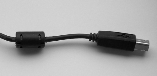
Minimising the effect of conducted noise is different to radiated noise. Conducted noise is usually best reduced by adding filtering to the cables where the noise is entering the system. This could be filtering by adding ferrite clamps to increase the inductance of a cable – the familiar lumps on power supply cables, USB cables etc.
The filtering has to reduce the noise while minimising the detrimental effects on the desired signal. Techniques such as twisted wire pairs and differential signaling (such as LVDS) can make circuitry tolerant of conducted noise without actually reducing the noise.
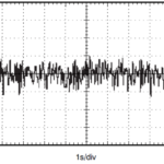
A spectrum analyser or oscilloscope with fast fourier transform (FFT) capability can be very helpful in tracking down where noise is coming from by helping to show the nature of the noise and identify specific frequencies which may not be obvious otherwise. Take the signal below:
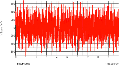
While it looks like random noise, and there is a random component there, if you look with an FFT you see this:
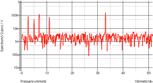
Then you will see that there are some very specific frequencies in there and in fact they are contributing to the majority of the “noise” seen in the oscilloscope trace. When you know some specific frequencies you have some clues to what might be the cause. For example, if one frequency is 250kHz and you have a switching regulator on the PCB or a connected PCB running at that frequency then that could be the cause. While these simulations may look contrived, they are actually representative of real situations I have encountered.
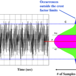
Random noise could be white, pink or otherwise, the cause can often be the circuitry itself. The strange terms “white” and “pink” refer to the noise spectrum when viewed with frequency as the x axis and drawing a comparison with light. White noise has an equal power per Hertz so looks like a flat, horizontal line of a spectrum analyzer. White light would also have a uniform power density. “Pink” noise refers to noise where the noise power density per Hertz is inversely proportional to the frequency. So, the noise increases with lower frequency. A light source which did that would look pink instead of white, allegedly, although I have never seen a light with that spectrum to be certain..
White noise is a common source of electronic noise in circuitry and is also called Johnson noise or thermal noise. It is caused by the collisions of the charge carriers in circuitry e.g. electrons, and the noise power is proportional to absolute temperature – hence the term thermal noise. This thermal dependence is also the reason why circuitry is sometimes cooled down – e.g. in cameras for astronomy. Thermal noise power is also proportional to resistance so a low value resistance helps to reduce noise, although sometimes you need a high resistance so that is not always practical. When amplifying low level signal it is better to use low value resistors where possible as they will contribute less to the overall noise. A good example would be the resistors used in an opamp based amplifier. The three spectra below show the noise from a perfect opamp with a gain of 40dB using 100k, 1M and 10M ohm feedback resistors. While the gain is the same in each case the noise is quite different because the resistors are the only noise source in this example:
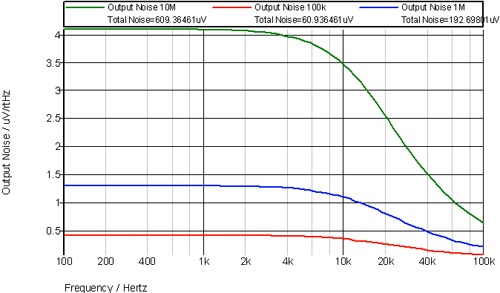
In a real opamp the situation with high value resistors would actually be worse because the opamp current noise would add to the output noise and the voltage due to the current noise would be higher with a higher resistance.
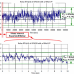
Pink noise is often seen with some white noise as well – not pure pink noise. So, rather than linearly increasing with reducing frequency you will see something like this:
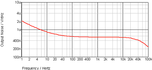
The noise increases with reducing frequency from around 20Hz. The drop-off above 20kHz is due to the opamp bandwidth that these simulations come from. The noise power is the sum of two noise spectra each of which can have multiple causes but they can be grouped to the white noise and 1/f noise sources. 20Hz is the point where they are making equal contributions to the total noise power. Above 20Hz the thermal noise is the dominant noise source and below 20Hz it is the 1/f noise. 1/f noise (pink noise or “flicker” noise) is found in various places – resistors have it, as do MOSFETs. In a MOSFET it is dependent on gate capacitance and the area of the transistor gate so to reduce the 1/f noise in CMOS IC design you would consider increasing the transistor gate area. This can result in some huge transistors in ICs, relative to the minimum available in a particular process.
Note that it is usual to talk of noise power. If you want to look at voltages or currents then you must remember that power is proportional to voltage squared in a resistor so you need to take care when summing noise voltages instead of noise powers – you must use the sum of squares to sum uncorrelated noise voltages.