(editor’s note: Intrigued by the problem? Have a question or another solution? Then click the “Read more” link and follow the conversation on EDAboard.com or log in to EDAboard and participate in the analog forum threads.)
Simulate a simple differential amplifier – My current source is 50 uA but the drain current of M16, M29 is only 3.09 uA. They don’t add up to 50 uA . Where is the rest of the current? Read more
Design capturing range 350Hz-550Hz by using HEF4046b PLL – I’m currently doing a project by using the HEF4046B PLL . I’m new to this chip. My requirement is to lock the PLL around 350Hz – 550Hz. My capturing range should be between 350Hz – 550Hz. Can somebody help me to select R2, R1 and C1 values? Read more
What is the definition of RS232 DB9 female? – I am confused about the RS232 9- pin female connector definition.
1. Could you clear if the following is right or not?
RS232 DB9 9pin female definition:
It should be DCE.
pin# pin name I/O
1 DCD O
2 TXD O
3 RXD I
4 DSR I
5 GND
6 DTR O
7 CTS I
8 RTS O
9 RI O
2. And I used MAX3237EIDBR to convert STM32 UART to RS232 by the aforesaid definition, but the RS232 can’t do the flow control. Why? Read more
How to design VCO buffer (Differential-to-single ended) – How do I design the differential- to single-ended VCO buffer? Constraints? Sizing of the MOSFETS? The circuit diagram is below. Read more

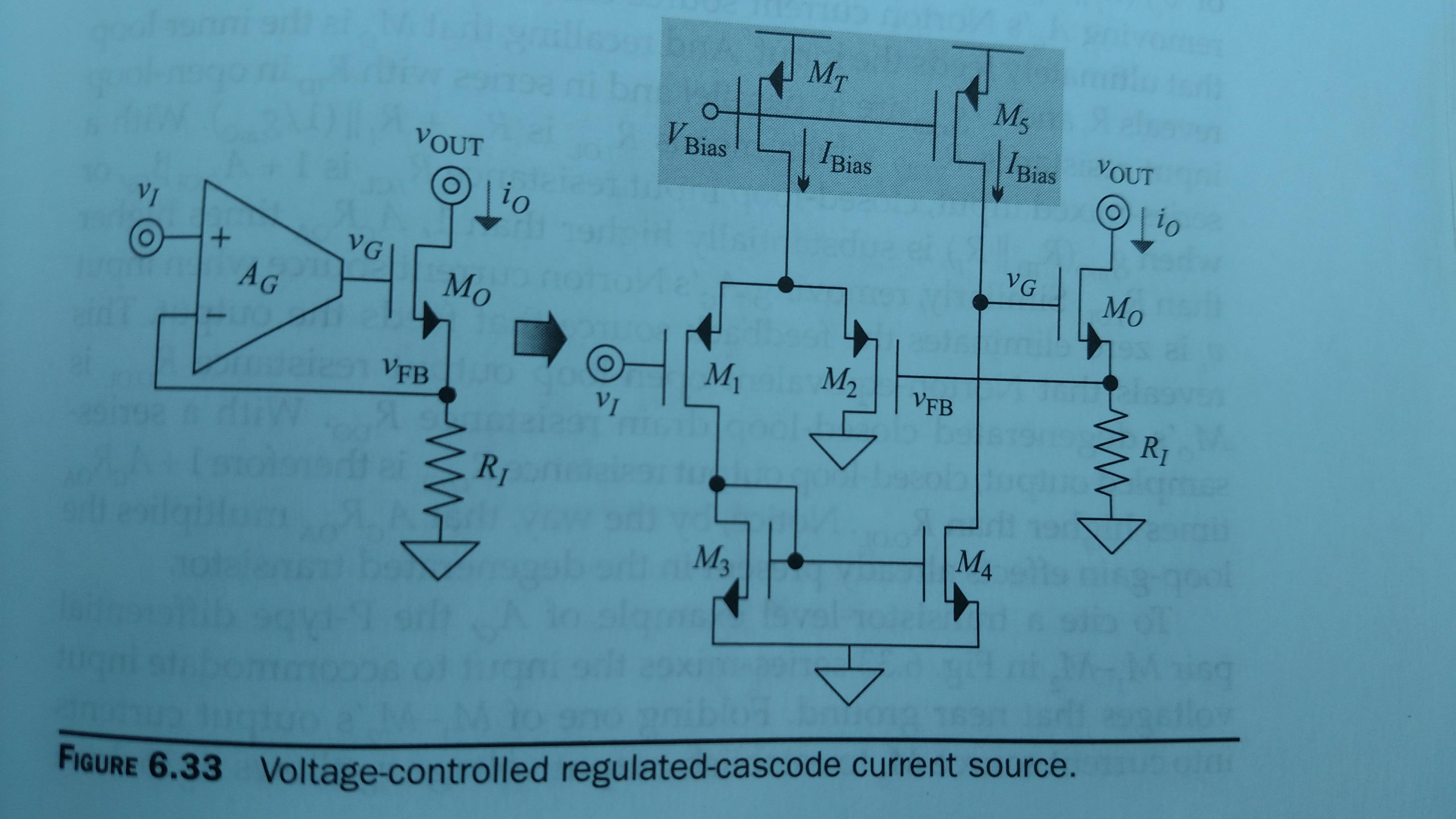
About this voltage-controlled current source – On the diagram, circuit on the right how does Vi comes across into Ri? It’s not obvious to me. Read more
Can anyone tell me what is the difference between filter and amplifier? If an active filter is designed using OP-AMP or OTA then we also have Difference between filter and amplifiergain of active element. It can amplify as well as filter out irrelevant frequency component from the signal. Similar is in an amplifier if amplifier is designed then also has gain and it amplifies signal. It can also work upto a certain frequency limit lets say if the amplifier amplifies signal upto 100KHz then it can also be like a low pass filter that allows frequency to pass upto 100KHz. So what’s the difference? Read more
The neutral potential and a battery ground – I want to measure the distribution voltage signal, the 110V @60 Hz or the 220V @50Hz. To do that I will use an ADC. If I don’t use an optocoupler to make an isolation, can I connect the battery ground and the signal neutral to have the same reference? Read more
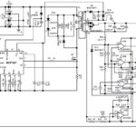
Issue with power supply – I created an alarm system for my factory.The concept of the project is, when I press the button, the horn will blow. The horn will blow two ways: continuously and with small interval time. My problem is, when I connected all power point in the circuit to UPS. it hangs down. I checked the voltage across the PIC’s VSS and VDD,RESET pins and it is 4.5V. But I don’t know what the problem is. Read more
Class AB dumb question – Can I use a class AB in a 2-stage Miller OTA? (Differential input to single output). If yes, how? Read more
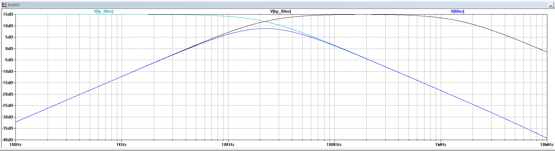
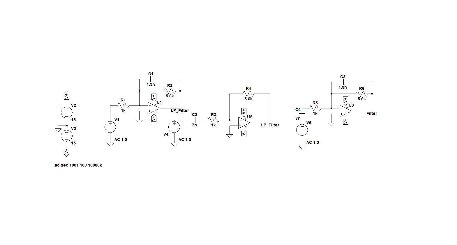
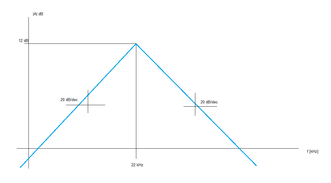
1st order pass-band active filter – I have an exercise to design a suitable 1st order pass-band active filter in order to satisfy the attached specification. My understanding of the exercise is the following:
– I have to use two 1st order filter in cascade (LP+HP filter) in order to have the 20dc/decade slope
– I assume that f=22 kHz is the -3dB cut-off frequency
– For the design, I assume that the 12dB gain is the one specified at fc=22 kHz, so the LP and HP filter has been designe to have a gain of 12 dB + 3dB
Below is picture of the designed circuit and the achieved frequency response. Do you think that am I correct? My understanding is that it is not possible to realize a filter with the specified shape because a certain rounding is not possible to avoid. What do you think? Read more