(editor’s note: Intrigued by the problem? Have a question or optional solution? Then click the “Read more” link and follow the conversation on EDAboard.com or log in to EDAboard and participate in the forum thread.)
Bipolar Junction Transistor with really tight tolerance on hFE – Do you know of a BJT with a really tightly toleranced hFE? We only need it for Vce = 20V max and Ic = 10mA max. Read more
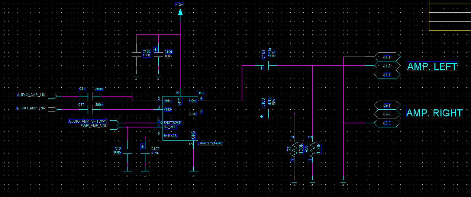
Audio power amplifier’s delay on start-up – I have a problem with my audio power amplifier circuit. As you see in this schematic there is 470u capacitor and 100k resistor in output stage.
When I power this circuit for the first time, the capacitor is fully discharged and the circuit works fine. But if I reset the power it takes about 2 minutes to work again and I think it’s all about the output stage. It is possible that input signal is not enough to reject charged DC in the capacitor. The load speakers are 3W and 4 ohm. Can you help me to fix this problem? Read more
Very stable single frequency audio oscillator – I need a very stable audio oscillator circuit that operates at a single frequency somewhere at 30Hz. A square wave is preferred and stability is the key point since it will be used as a reference to lock a higher frequency oscillator. I would use a multivibrator, but how stable it should be if using low ppm resistors and capacitors? In that case, can it be made so that the timing resistors are made high and the capacitor very low values? Read more
How to design eMOSFET switch -I am designing an E-Mosfet (FQP3N30) as a switch. How can I design the value of drain resistance Rd? My load is a coil valve (internal resistance is 33ohm to 70Ω, current is 500mA) that is connected to the output of the MOSFET (drain). Could you please tell me how can I design my drain resistance in order to get 300V and 0V volts at the output through switching? Read more
Strain gauge calibration – I’m looking for a low-cost strain guage that can feel 1g to 1kg tension on a small aluminum plate. I understand that there are several methods to sense the change in the resistant of the strain gauge. Can some one recommend the best to use (half bridge, full bridge?). And how do I calibrate the bridge? Read more
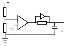
Power op amp from discrete – I just designed this and I’m wondering if it would work in real life? Q1 and Q2 are bdx53c/54c or bd679/680. Read more
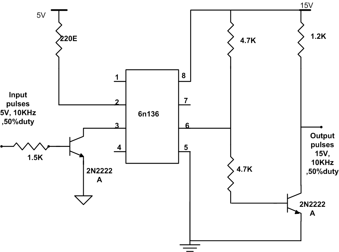
Optocoupler circuit deadband creation – I have a circuit as shown. I am getting a delay in the output in the range of about 5-6us. I am giving a PWM pulse 10Khz, 5V and 50% duty ratio. The output is 15V. I would like to know what causes the delay in output and if there is a way to control this. Read more
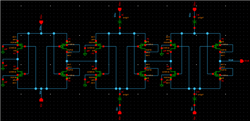
Impedance matching of RF energy harvesting system – I am designing an RF energy-harvesting prototype system. However, I face some problems which are:
1. Which type of matching network (between antenna and rectifier) is suggested to use?
2. How to calculate the input impedance of the rectifier? The rectifier design is using the MOSFET transistor as the diagram below. I have no idea on calculating it. Read more
Why is an input bias current of an opamp constant – When we consider an input bias current of an opamp, it is constant. For example, if there is a simple inverting amplifier without an input signal, the output voltage will be the input bias current x the feedback resistor, and the output voltage only depends on the feedback resistor. Why is the input bias current constant? Why isn’t it affected by the resistor or input impedance? Read more
Electrolytic capacitor and ceramic capacitor – I am using a 10uF electrolytic capacitor on a breadboard to test the circuit. The diagram shows part of the circuit. When I use an electrolytic capacitor, the RC time constant is about 8 seconds and when I fabricate the circuit on a PCB and use an SMD ceramic capacitor (non-polarized), the time constant drops to about 2 seconds.
I desoldered the ceramic capacitor and put in an electrolytic capacitor into the PCB and the time constant works as designed which is 8 seconds. Why does this happen? Read more