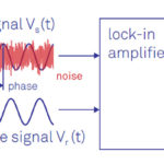
The lock-in amplifier allows tiny signals from sensors to be captured with precision despite unavoidable noise limitations and other signal-chain test and measurement challenges.
There are some basic test and measurement instruments common to scientific labs and engineering benches of all types, whether electronic, biomedical, chemical, optical, or mechanical. Among these are the digital voltmeter, oscilloscope, frequency counter, and signal generator, as just a few examples. At the other end of the instrumentation range are highly specialized instruments which are useful only to their individual specialized disciplines, such as a DNA sequencer for biomedical research or a multi-gigahertz spectrum analyzer for advanced wireless links such as 5G.
However, there are also advanced instruments which cut across multiple disciplines. While they would not be found in a basic lab, they would be fairly common in many higher-end installations. One example is the lock-in amplifier or LIA.
What is a lock-in amplifier, what does it do, and why is it needed? This article will explore those issues and related topics. It will focus on the basic LIA and not delve into the more highly advanced models with additional features and functions available; the References at the end will provide links to sources for those.
Lock-in amplifiers have been used since the 1930s with designs based on vacuum tubes. Still, transistors, high-performance low-noise op amps, and digital techniques have improved their performance while adding useful features and making them less “finicky” as well, of course.
Q: In brief, for what is the LIA used?
A: LIAs function in two roles:
- It can recover low-level signals despite the presence of an overwhelming noise background which is far greater than the desired signal.
- Alternatively, it can provide high-resolution measurements for relatively clean signals over several orders of magnitude and frequency.
Q: Can’t you use a high-gain amplifier to recover a weak signal?
A: No, it’s not that simple. As usual, noise complicates the situation and establishes a limit on performance. Even if the signal of interest has no noise itself (only a possibility in theory, as all signals have some noise), the front-end amplifier used to “gain it up” has its own internal noise, which would overwhelm the signal itself.
Q: Can’t you just use a lower-noise amplifier?
A: That’s the first step towards a solution, and there are amplifiers – here, op amps – with extremely low noise. But it’s not just the amplifier with internal noise: all components such as resistors have their own thermal noise, which is generally proportional to temperature. To attenuate that noise, that amplifier circuit needs to be cooled. This is impractical for most situations, although it is done in specialized cases, such as receivers for signals from deep-space probes.
Q: Is noise the only problem?
A: No, there is a problem with capturing and amplifying a low-frequency signal (often called “DC” even though it is not strictly DC). The signal-chain components will have thermal drifts, offset voltages, leakage currents, bias currents, and other slowly changing variations, just like the signal of interest. If these variations were static and unchanging, they could be calibrated out up-front with some effort. Instead, they vary slowly and somewhat randomly and therefore are indistinguishable and non-separable from the signal of interest.
Q: What would the basic, non-LIA approach to capturing a low-level signal?
A: Consider a typical set-up of current signal from a photodetector (phototransistor) in an optical-physics experiment as an example (Figure 1). While we usually think of photocurrents as being on the order of 10 milliamps (mA) or more, in many experimental cases, that current may be orders of magnitude lower, in the nanoamp (one nA = 10-9 A), picoamp (1 pA = 10-12 A), or even femtoamp (1 fA = 10-15 A) range. In these cases, the internal noise will overwhelm the current.
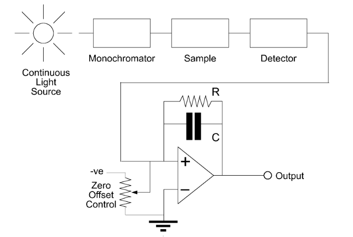
The monochromator is a specialized, non-electronic, optical-bandpass filter which largely eliminates light outside the desired wavelength band to prevent that light from adding to the photodetector (sensor) stimulus. The photodetector feeds its output to a basic low-drift amplifier. The voltage output from the amplifier is then measured using a conventional voltmeter (not shown).
Q: What’s the problem here?
A: There are two problems: first, the DC signal from the detector will present a non-zero current output even with no optical input due to its leakage current. Second, there is no way of separating the output signal due to the desired signal from any output, which results from stray light entering the detector (the monochromator filter and overall set-up are not perfect).
Q: What is one approach to solving this dilemma?
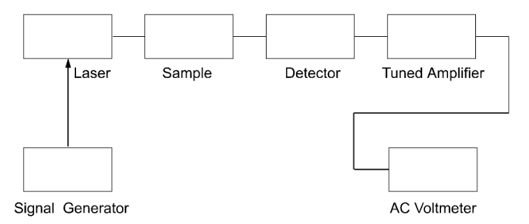
A: The widely used solution is to modulate the light source with a periodic signal, usually a sine or square wave. In optics, this is often done using a mechanical light “chopper” (a rotating disk with slits) which sounds crude but has a long historical basis and is actually widely used even today. The other way is to modulate the light source itself, which seems better. Still, it is often difficult to actually achieve since many light sources need to be “on” constantly for optimal performance, and turning them on/off at high rates affects their performance. The chopper does this modulation entirely independent of the light source or the need to control it.
Q: How does modulating the signal source help?
A: Once the desired light source as the signal is modulated, it can be demodulated using one of several available techniques for separating a signal from its modulated carrier (Figure 2). The modulated signal is passed through a highly selective filter (a tuned amplifier), leaving only the desired signal. Performance drifts and other problems with the input signal are thus largely eliminated, at least in principle.
Q: Seems like the problem is solved. What’s the issue?
A: There are several:
- First, the tuned amplifier must have a very high-Q, highly selective filter centered on the modulating frequency to be effective. But these high-Q filters are not perfect nor stable enough with changes in temperature, component aging, and other factors. Thus, the filter passband drifts, thus degrading its performance with respect to the signal of interest.
- Second, filters add noise to the signal path, and this noise also corrupts the recovery of the desired signal.
- Third, if the mechanical chopping frequency or electronic signal generator driving the laser or other light source has long-term drift or short-term jitter– as they inevitably will have, to some extent – the filter passband will be in the wrong place in the spectrum, and the signal path and filtering will be compromised. While it is possible to construct a tracking filter, adding to the complexity brings new error and noise sources and is only effective for longer-term drift but not jitter.
For those who want to explore the signal versus noise and signal-chain and capture issues, some of the references at the end go through the math in detail with equations and numbers showing the limitations due to front-end channel noise, drift, jitter, offsets, and other imperfections.
Part 2 of this article explains how the lock-in amplifier overcomes the shortcomings of the tuned, narrow-filter approach.
Related EE World articles
- Multi-device synchronization for lock-in amplifiers and arbitrary wave generators
- Lock-in amps get AM/FM modulation option
- FAQ: What is Phase Locked Loop (PLL)?
References
- Ametek Technical Note TN100, “What is a Lock-in Amplifier?”
- Perkin Elmer (now Ametek) Technical Note TN102, “The Analog Lock-in Amplifier”
- Perkin Elmer (now Ametek) Application Note AN 1003, “Low Level Optical Detection using Lock-in Amplifier Techniques”
- Zurich Instruments, “Principles of lock-in detection” (includes video tutorial)
- Zurich Instruments, “Principles of lock-in detection and the state of the art”
- Stanford Research Systems, Application Note 3, “About Lock-In Amplifiers”
- Lehigh University, “Lock-in Amplifier and Applications”
- All About Circuits, “Basic Fundamentals of Lock-In Amplifiers”
- SPIE, “Applications of Lock-in Amplifiers in Optics”
- Journal of Chemical Education, “Low-Cost, High-Performance Lock-in Amplifier for Pedagogical and Practical Applications”
- Science Direct, “Application of Lock-In Amplifier on Gear Diagnosis”
- American Journal of Physics, “A basic lock-in amplifier experiment for the undergraduate laboratory”
- University of Tennessee, “A Lock-In Amplifier for Fluorescent Light Detection”