I recently had cause to look again at thermocouples after not having used them for many years. While they may seem a little old fashioned when you can measure temperature with a simple IC or a complex IC with an I²C or SPI interface such as the Analog Devices ADT7410, thermocouples still have their uses. For example, if you want to measure to 1000°C or more or -200°C.
Thermocouples rely on the Seebeck effect whereby a junction of two dissimilar metals produces a voltage. While this sounds simple in principle, there are a couple of issues. One issue is that the voltage generated by the temperature of the junction is not absolute as it is partially canceled by other junctions of dissimilar metals in the signal path, and the other issue is that the output voltage is not linear.
The first problem is caused by the fact that you need to connect your thermocouple to your system and sooner or later you will end up changing both metals to another metal, probably copper. This diagram illustrates the problem assuming a chromel-alumel (type K) thermocouple.
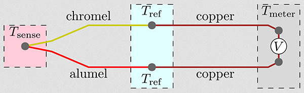
The point where the metals change to copper is the “cold junction” – labeled Tref in this diagram. It is important that these two points are at the same temperature otherwise you will introduce some inaccuracy into the system. Also, you need to know the temperature of that point, Tref. If Tref is the same temperature as Tsense then you will see no voltage – the voltage generated at Tsense will be canceled out by the two voltages generated at the Tref points. While you could put the Tref junctions in an ice bath to maintain a stable reference “cold junction” temperature, that is not a very practical solution. Most systems will simply use another temperature measuring method to measure Tref, which will usually be at “room temperature” or at least within the operating temperature range of electronic circuits which may not be the case with Tsense.
If you want to have the thermocouple a long way from the electronics then the long wires to the electronics need to also be thermocouple wire, because you need to be able to measure the temperature of the change to copper wire/PCB tracks and that will be near your electronics.
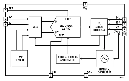
Both Tref points must be at the same temperature to avoid errors so will be close together and also close to whatever circuitry is measuring the cold junction (or reference junction) temperature. An IC such as the Linear Technology LTC2485 can do some of this work for you – it combines an ADC (analog to digital converter) and temperature sensor. You will still need to calculate the temperature from the measured voltage and the reference temperature and correct for linearity in your software.
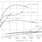
This raises the issue of linearity. If you assume 40.6µV/°C for a type K thermocouple then you will have an error of up to 2.5°C over 0°C to 400°C. Other thermocouple types can have errors up to 25°C over that temperature range unless you correct for the non-linearity, and even larger errors over a larger temperature range. The required correction is often done with lookup tables rather than polynomial approximations as it is less processor intensive.
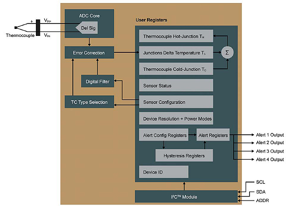
One other consideration is “which thermocouple type”? Thermocouple types are usually abbreviated to a letter such as K, J, T N etc. The K type is common and reasonably linear over a limited range. There are a lots of other choices which are either good at low or high temperatures with some usable to 2500°C or more. So the temperature range you need to measure is a significant consideration. Cost may also be important and significant – some use more expensive metals and that can be expensive if you need long wires to the sensing point. Also, bear in mind the output voltage per °C. A low output will make you more susceptible to noise. While thermocouples have a low impedance they are still susceptible to noise because the output voltages are low. Twisting the wires together helps (with insulation to stop them touching) as does low pass filtering, particularly to remove 50/60Hz mains pickup. The new Microchip MCP9600 is an interesting solution as it also corrects for thermocouple non-linearity for 8 different types and has an I²C interface.