The previous parts of this article explored the photomultiplier tube (Part 1 and Part 2), which is based on a simple, fairly clear physics principle, although building a high-performance PMT is an art and requires various skills, of course. This part looks at a microwave/mm-wave amplifier called the traveling wave tube (TWT – often pronounced “twit”) or traveling wave tube amplifier (TWTA), which is based on a much more complicated understanding of electromagnetic theory and applications. Along with the klystron, the TWT is in what is called the class of linear-beam microwave devices.
Q: What is the problem which the TWT addresses?
A: There is a need for higher-power amplifiers which operate in the 1-10 GHz range and much higher, and also can deliver kW and tens of kW of power and more. The combination of frequency and power is a very difficult one to serve.
Q: Isn’t “solid state” using SSPAs – solid-state power amplifiers – the way this is now achieved?
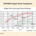
A: SSPAs can deliver power at higher frequencies, and they have made great progress in the last few years, both with individual devices and paralleled ones. However, they still cannot achieve the combination of frequency and power that TWTs can, especially when you need hundreds or thousands of watts above 10 GHz, or into the “mmWave” spectrum from 30 to 300 GHz. While TWTs are originally used beginning at around 300 MHz, the use of TWTs for high-power applications at these lower frequencies have largely been made obsolete by SSPAs. However, as applications go into the tens of GHz, TWTs still have a major role.
Q: What is in the TWT?
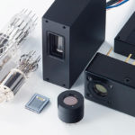
A: The TWT is an evacuated cylinder (usually glass, sometimes ceramic) with an electron “gun” comprised of a heated cathode, anode plates, a helix-shaped energy path, focusing magnets, and a collector anode (Figure 1). In addition, there is a high-voltage power supply for the anode, a low-voltage supply for the cathode heater, and additional control and monitoring circuits.

Q: What’s the operating principle of the TWT?
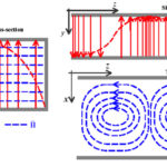
A: In a word, complicated. It uses a longitudinal electron beam to interact continuously with the field of a wave traveling around the tube (Figure 2). There is an interface circuit for coupling of the external RF circuit to the slow-wave structure at the input and one at the output. A helical circuit capable of propagating a slow wave is spaced closely around the beam, and it is proportioned so that the phase velocity of the wave is small compared to the speed of light. The electron stream produced by the gun travels along the axis of the tube, and is finally collected by the anode.
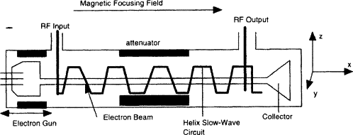
When a wave is launched on the circuit, the longitudinal component of its field interacts with the electrons and travels in approximate synchronism with it. Therefore, some electrons will be accelerated, and some will be decelerated, which results in continual phase-shifting of the electrons with respect to the wave. This modulated electron stream then, in turn, induces additional waves in the helix, in a mutual-reinforcement interaction, which continues along the length of the tube. Thus, the electron stream “gives up” some of its energy as RF energy to the circuit. The output is an amplified version of the input RF waveform.
Q: What are some of the attributes of the TWT?
A: With proper design and larger physical structure, they can produce tens of kW and even MW of power. Further, as a result of the nature of the continuous interaction between the wave traveling on the broad-band circuit and the electron stream, they do not have the gain-bandwidth limitations of conventional vacuum tubes, and so can have bandwidths of two and even three octaves. This makes them very useful as “general purpose” amplifiers reaching into multi-GHz applications.
Q: What is the size of a TWT?
A: It depends on the power level and frequency. Smaller ones are about 12 to 24 inches long (25 to 50 cm) with a diameter of about 1-2 inches (2 ½ to 5 cm). They are small enough that they are fitted into some aircraft for basic radar and even ECM (electronic countermeasure) subsystems. Larger ones can be the size of an equipment rack cabinet or even larger.
Q: Where are TWTs used?
A: Obviously, where the application demands output at the higher frequencies, or large amounts of power at moderate frequencies, or both. It is used in some desktop test and measurement equipment, where it makes sense and best available option, and even the synthetic aperture radar (SAR) of some UAVs (unmanned drones). One notable area where TWTAs are still are widely used is in communication satellites. Their power and frequency capabilities are a good fit, and they can handle frequencies over a very wide band, which is desirable for in a satellite functioning as an orbiting “repeater.” Due to the frequencies and power levels, they are often used with waveguides (References 10 and 11). Also, as a VED, it is electrically rugged and resistant to the unavoidable radiation in space-related applications.
Q: I’d like to know more, where can I look?
A: References 12 to 15 are just a few of the sources which give additional insight into their operation from different perspectives; a huge number of papers and books are available, many beginning with Maxwell’s equations. The TWT is such an important and widely used VED that considerable academic analysis, technical discussion, and practical work has been done about them, with many books and article available all levels.
This part has looked at the basics of the TWT. The next and final part looks at some other issues related to it and its “competition,” the SSPA.
References
- EE World, “Magnetron, Part 1: Application and operating principles”
- EE World, “Magnetron, Part 2: History and future”
- Wikipedia, “Photoelectric effect”
- Khan Academy, “Photoelectric effect”
- Encyclopaedia Britannica, “Photoelectric effect”
- Scientific American, “Einstein’s Legacy: The Photoelectric Effect”
- Florida State University, “Concepts in Digital Imaging Technology: Photomultiplier Tubes”
- Hamamatsu Photonics, Photomultiplier Tubes: Basics and Applications,
- Hamamatsu Photonics, Data sheet Hamamatsu R3896
- EE World, “What are RF waveguides? Part 1: context and principles”
- EE World, “What are RF waveguides? Part 2: implementation and components”
- Radar Tutorial/EU. “Traveling Wave Tube” (very good description and images)
- Elsevier Science Direct, “Traveling Wave Tube”
- Tutorials Point, “Travelling Wave Tube” (readable, somewhat simplified)
- Microwaves 101, “Traveling Wave Tubes” (has close-in photos of custom made, non-commercial TWTs)
- Engineering and Technology History Wiki, Rudolf Kompfner
- Microwave Journal, Military Microwaves Supplement, “TWTAs Still Dominate High-Power and mmWave Applications”
- dB control/Heico, “What’s Better – TWTAs or SSPAs?
- Greek Microwave Group, “TWTs vs SSPAs”
- Microwave Journal, “ABI Research Finds Microwave Tube Market Still Strong at Over $1B for 2018”
- Semantic Scholar, “Communication satellite power amplifiers: current and future SSPA and TWTA technologies”


