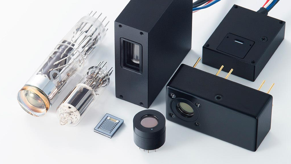
Maybe we can’t live with them, but we can’t live without them, at least not yet: the photomultiplier tube and the traveling wave tube are two vacuum electron-tube devices that are still viable and needed in our solid-state world.)
It’s widely accepted conventional wisdom that almost “everything” has gone solid state and that vacuum tubes are technology dinosaurs. While that may be mostly true, there are exceptions. These include the magnetron RF source, which is in every consumer microwave oven and many commercial ones (References 1 and 2), the extreme high-power tubes used for commercial AM and FM broadcast stations, and specialty tubes as X-ray sources.
But there are some important niche applications were vacuum tubes still are the best solution, despite the availability of functionally similar solid-state equivalents. Parts 1 and 2 of this FAQ will look at two very different tubes in this group, the photomultiplier tube (PMT), while Parts 3 and 4 will look at the traveling wave tube (TWT) as the core of the traveling wave tube amplifier (TWTA). In fact, manufacturers of these devices prefer to call them “vacuum electron devices” (VED) as it is a more descriptive name for the entire group rather than the bland “vacuum tube”. It also puts them on a plane comparable to solid-state devices.
Q: What is the function of the PMT?
A: As the name states, it is a tube that captures and converts impinging photons into many electrons as an embodiment of the photoelectric effect (References 3 through 6). Note that this effect was observed in the late 1800s but posed a significant challenge to physicists, since the experimental results were contradictory and could not be explained by the physics of the time — until Einstein provided a quantum-based explanation, work for which he was awarded the Nobel Prize in 1921.)
Q: Why is a PMT needed?
A: In general, capturing individual or a low number of photons is difficult; photons do not like to be “caught” in the sense that the very act of sensing them also transforms them. Unlike voltage or power, which are “macro” phenomena, the photons are a micro phenomenon as it is a discrete bundle of energy, as defined by quantum theory. Devices which convert low levels of photons — as defined by their quantity and each photon with a specific amount of energy determined by their wavelength — must do so in the presence of unavoidable electrical noise, which makes the measurement difficult.
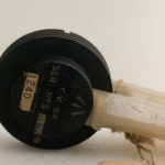
Q: What is the PMT, and what are its internal components?
A: The PMT is a light-sensitive, cold-cathode vacuum tube (no heated filament, as in a conventional vacuum tube) (Figure 1 (in fact, having a heated filament which causes the cathode to emit electrons would negate the intended function).
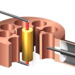
It has three main elements (Figure 2):
- a photocathode which absorbs the incident impinging photon; it is made of a photosensitive material;
- an arrangement of electrically charged “dynodes” which provide the gain of the PMT; these are made of a special coating deposited onto a substrate electrode made of nickel, stainless steel, or copper-beryllium alloy;
- an anode to collect electrons
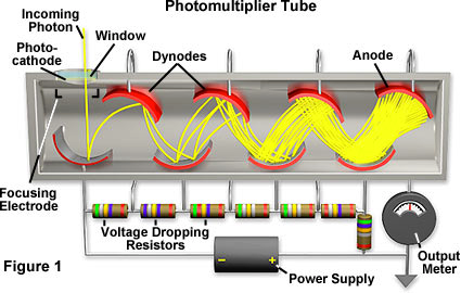
Q: How does the PMT function?
A; When the incident quantum of light energy – what we call a photon – passes through the PMT’s glass or quartz window and hits the photocathode, it is absorbed. This results in a possible emission of an electron into the PMT’s internal vacuum (this is the action of the photoelectric effect). Next, the electron (if one was emitted) is accelerated by the internal electric field (due to a potential of about a thousand volts) towards the first dynode. When this primary electron strikes that dynode, it shares some of its energy with the dynode’s electrons, and some fraction of these electrons escape into the vacuum, in a process called secondary emissions.
These new electrons then accelerate to the second dynode, and the process continues and cascades. After a series of dynodes, the anode collects the electrons from the final dynode and sends them in a conventional current flow in a circuit. As a result, a single photon has been transformed into a stream of electrons in a wire, a current.
Q: What are some applications which use PMTs?
A: There are many, and they are often not obvious. There are scientific and astronomical applications, of course, but also flow cytometry, which studies, counts, and analyzes biological cells; in fact, a sophisticated flow cytometer may use a PMT as well as the other non-PMT photon sensor in a single instrument.
Part 2 of this PMT article looks at some additional issues related to PMTs.
References
- EE World, “Magnetron, Part 1: Application and operating principles”
- EE World, “Magnetron, Part 2: History and future”
- Wikipedia, “Photoelectric effect”
- Khan Academy, “Photoelectric effect”
- Encyclopaedia Britannica, “Photoelectric effect”
- Scientific American, “Einstein’s Legacy: The Photoelectric Effect”
- Florida State University, “Concepts in Digital Imaging Technology: Photomultiplier Tubes”
- Hamamatsu Photonics, Photomultiplier Tubes: Basics and Applications,
- Hamamatsu Photonics, Data sheet Hamamatsu R3896
- EE World, “What are RF waveguides? Part 1: context and principles”
- EE World, “What are RF waveguides? Part 2: implementation and components”
- Radar Tutorial/EU. “Traveling Wave Tube” (very good description and images)
- Elsevier Science Direct, “Traveling Wave Tube”
- Tutorials Point, “Travelling Wave Tube” (readable, somewhat simplified)
- Microwaves 101, “Traveling Wave Tubes” (has close-in photos of custom made, non-commercial TWTs)
- Engineering and Technology History Wiki, Rudolf Kompfner
- Microwave Journal, Military Microwaves Supplement, “TWTAs Still Dominate High-Power and mmWave Applications”
- dB control/Heico, “What’s Better – TWTAs or SSPAs?
- Greek Microwave Group, “TWTs vs SSPAs”
- Microwave Journal, “ABI Research Finds Microwave Tube Market Still Strong at Over $1B for 2018”
- Semantic Scholar, “Communication satellite power amplifiers: current and future SSPA and TWTA technologies”