Understanding the role and implications of impedance in RF transmission lines and antennas is vital to successful system performance.
Part 1 of this article looked at the basics of impedance matching and power transfer. This part looks at the closely related topic of nominal impedance and VSWR.
Q: Why all this worry? Aren’t RF systems designed to be at 50-ohms with no reactive component?
A: Only in dreams. While designers wish everything was a resistive-only 50 ohms, the reality is that the output and input impedances of many components of circuits are not 50 ohms and not purely substance. This is a function of the physics of the construction, strays and parasitics, electromagnetic theory, and other considerations that cannot be controlled or changed. As a result, designers have to learn to live with and work with the reactive impedances, even if they are not at 50 ohms, even if they are purely resistive. The 50-ohm value is a goal and often used as a normalized or target value.
Q: We sometimes see an RF system with a nominal impedance of 75 ohms – what’s the story there?
A: While most RF designs use resistive 50-ohm impedances as their nominal value, video systems have traditionally used 75 ohms and still do. The reason for both 50 and 75 ohms is both technical and historical. First, those two resistance values are close to the natural value that impedances have using a coaxial transmission line of convenient dimensions – the first such lines were made of copper plumbing pipe of different diameters, with one inserted into the other.
Second, there’s also an unavoidable difference that is a function of transmission-line attributes. Every transmission line (usually coaxial cable, but can also be open wire) has issues with the maximum voltage/power it can handle as well as insertion loss (dB) at a given size. Analysis shows that higher impedance such as 75 ohms has a lower loss – a video-system priority, especially in the “early” days – while lower impedance such as 30 ohms has better power-handling capability (Figure 1).
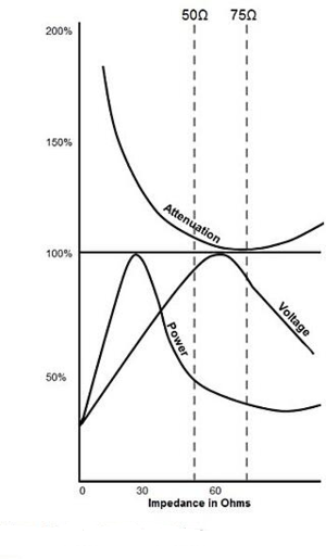
Thus, 50 ohms turns out to be a good compromise between those priorities. References 3, 4, 5, and 6 give more background and even explain some of the “lost” histories of this choice. Note that video designers regard 75 ohms as the “natural” nominal value while RF designers consider 50 ohms to be the “more-correct” value. Since most RF work is done at 50 ohms, we’ll assume that is the nominal design-target value.
Q: What’s VSWR?
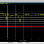
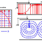
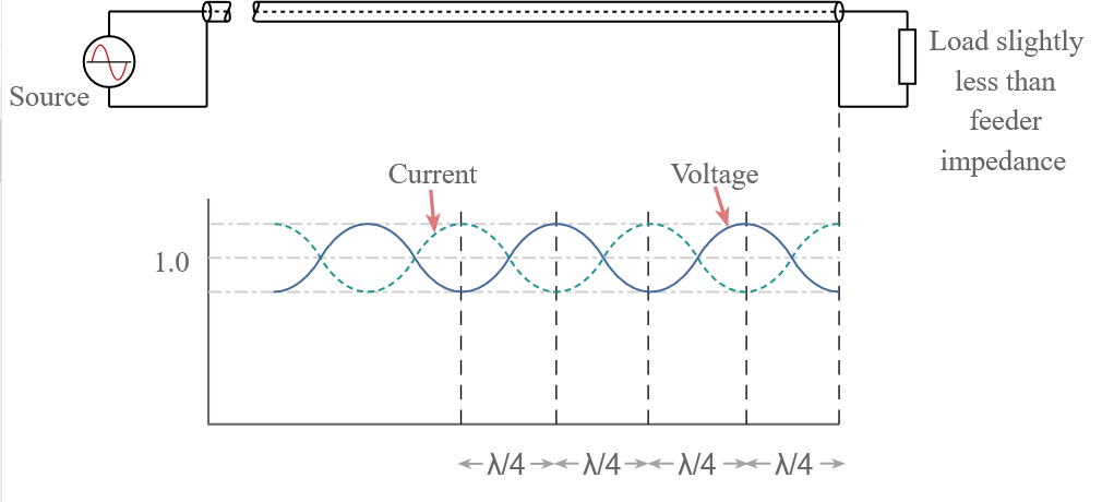
A: VSWR (usually pronounced vis-wahr) is short for voltage standing wave ratio (often also called SWR or standing wave ratio, with the “vertical” omitted) and is the manifestation of impedance matching and mismatch on transmission lines. When RF energy is injected into a transmission line and propagates along the line, it continues unimpeded until it hits an impedance mismatch. Some of the impinging energy will reflect to the source, with the amount dependent on the magnitude of the mismatch (Figure 2). These reflected waves, in turn, create “standing waves” of RF energy along the transmission line (Figure 3).

Q: What’s the underlying theory?
A: Transmission line impedance, propagation, matching, and related issue have been extensively studied and analyzed as they are very important topics. In simplified form:
VSWR is the voltage ratio of the signal on the transmission line:
VSWR = |V(max)| / |V(min)|
where V(max) is the maximum voltage of the signal along the line, and V(min) is the minimum voltage along the line.
It can also be derived from the impedances:
VSWR = (1+ Γ)/(1- Γ)
where Γ (gamma) is the voltage reflection coefficient near the load, derived from the load impedance (ZL) and the source impedance (ZS):
Γ = (ZL-ZS)/(ZL+ZS)
If the load and transmission line are matched, Γ = 0, and VSWR = 1.0 (or 1:1).
(Note that the reflection coefficient is also known as s11 or return loss when using s parameters.)
Q: How is VSWR expressed?
A: It is a unitless ratio and, as such, can be expressed as a ratio, such as 1.5:1, or 2:1, or just a single number, with the understanding that the denominator of the ratio is 1.
Always keep in mind that the source and load impedance is usually a function of frequency, so VSWR will also be frequency-dependent. Therefore, when providing a VSWR number, the frequency should also be stated.
The next section looks at the implications of non-unity VSWR and how it is measured.
Related EE World Content
What are the functions and principles of S-parameters (Part 1)?
What are the applications and measurements of S-parameters? (Part 2)
RF power amplifier, Part 1: Functions and Elements
Solar cells and power, Part 2 – power extraction
Measuring antenna properties
Using the Smith chart for Impedance matching, Part 1
Impedance matching and the Smith Chart, Part 2
The difference between SWR and TDR meters
Measure power in complex RF signals
What are RF waveguides? Part 1: context and principles
What are RF waveguides? Part 2: implementation and components
References
- Wikipedia, “Maximum power transfer theory”
- Tutorials Point, “Maximum Power Transfer Theorem”
- Microwaves 101, “Why Fifty Ohms?”
- Belden, “50 Ohms: The Forgotten Impedance”
- High Frequency Electronics, “There’s Nothing Magic About 50 Ohms”
- Wilson Amplifiers, “50 Ohm vs. 75 Ohm: Which is Best For You?”
- Wikipedia, “Standing wave ratio”
- Antenna-Theory, “VSWR (Voltage Standing Wave Ratio)”
- Electronics Notes, “What is VSWR: Voltage Standing Wave Ratio”
- Electronics Notes, “How to Measure VSWR: approaches & test instruments”
- Maxim Integrated Products, “Glossary Definition for impedance-matching”
- Maxim Integrated Products, “Glossary Definition for VSWR”
- Nuts and Volts, “Impedance Matching”
- Mini-Circuits, “Impedance Matching Devices”
- Mini-Circuits, “Demystifying Transformers: Baluns and Ununs”
- NI (National Instruments), “Impedance and Impedance Matching”
- Tektronix, “Introduction to VNA Basics”
- Triad Magnetics. “Understanding the Maximum Power Theorem”
- QSL Net, “50 MHz (6 Meter) Tuner Circuits”
- QSL Net, “Six Meter Transmatch (Tuner)”
- M0UKD (Amateur Radio Personal Site), “End Fed Half Wave Antenna Coupler (EFHW)”
- Altium Limited, “Stripline vs Microstrip: PCB Routing Differences and Guidelines”
- Researchgate, “A Self-Complementary 1.2 to 40 GHz Spiral Antenna with Impedance Matching”