Understanding the role and implications of impedance in RF transmission lines and antennas is vital to successful system performance.
The importance of impedance matching, minimizing reflections, and keeping a low VSWR means these topics have been studied extensively, ranging from analytical perspectives through many physical designs and implementations. This section looks at some matching techniques.
Q: What are some approaches to impedance matching?
A: There are four basic ways to implement impedance matching:
- Resistive matching: only suitable when the mismatch is purely resistive, with no reactive components.
- Transformer matching via turns ratio: again, only suitable when the mismatch is resistive, with no reactive components.
- LC matching using inductors and capacitors as series and parallel (shunt) elements in a variety of topologies.
- Transmission line matching with a specifically calculated length of transmission line (quarter-wave) and standard or custom-made impedance value.
Q: What’s the simple resistive match?
A: The most common lossy impedance matching device is the L-pad, also known as the minimum loss pad (Figure 1). It uses a series resistor and a shunt resistor. The configuration that results in the lowest insertion loss while still matching impedances.
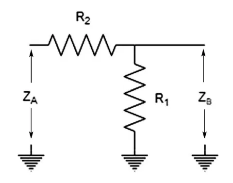
Using Ohm’s law, Equation (1) represents the impedance as seen by ZA, and Equation (2) represents the impedance seen by ZB.
(1) ZA = R2 (R1 + ZB)/R2 + (R1 + ZB)
(2) ZB = R1 (R2 + ZB)/R1 + (R2 + ZA)
which works out to:
(3) R1 = ZA × α
(4) R2 = Zb/α
Where α = √(1- (ZB/ZA))
For the common case of ZA = 75 Ω and ZB = 50 Ω, R1 = 86.6 Ω and R2 = 43.3 Ω, which also yields a minimum loss of 5.7 dB. Note that the resistive match can be used down to DC; the upper-frequency limit is a function of construction and unavoidable parasitics.
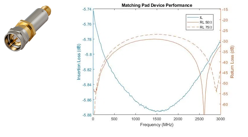
You can buy this matching “pad” complete with connectors (Figure 2). The Mini-Circuits SFQFM-5075+ is a connectorized resistive matching pad designed for optimal return loss from DC to 3000 MHz. It has less than 25 dB return loss and an expected 5.7 dB insertion loss. It also features an SMA-female and a quick-connect F-type male connector to be compatible with the likely cable with which it will be used.
Q: How is a transformer used for impedance matching?
A: Just as a transformer’s turns ratio of a transformer can step a voltage up or down, the turns ratio will also transform and match impedance. The impedance ratio between the primary and secondary sides of a transformer is determined by the ratio of the number of turns on the secondary side (n2) to the number of turns on the primary side (n1):
Z2/Z1 = (n2/n1)2
Again, for the widely 50 Ω to 75 Ω transformer, the impedance ratio is 1:1.5 and the turns ratio is 1:1.22, which can be implemented by 4.5 turns on the primary (50 Ω) side and 5.5 turns on the secondary (75 Ω) side. The transformer can be built with very low parasitics and very wide bandwidth and is used in the hundreds of megahertz and even gigahertz range. Larger ones can also handle substantial amounts of power, which is a benefit in higher-power transmitters.
Q: What else is unique about transformer-based impedance matching?
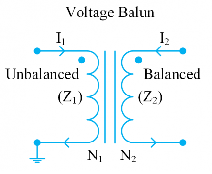
A: Dual-winding transformers inherently provide galvanic isolation between input and output (the alternative single-winding, “tapped” autotransformer is not isolated). In many cases, this is a useful or even mandatory electrical consideration. They also can transform a grounded, single-ended (unbalanced) impedance into an ungrounded, floating (balanced) impedance.
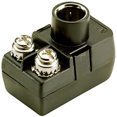
For example, one widely used arrangement is called a “balun” (sort for balanced/unbalanced) which provides an impedance match between a 75 Ω coaxial transmission line and the inherent approximately 300 Ω (actually 270 Ω ) impedance of a folded dipole antenna (Figure 3).
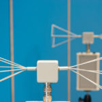
You can buy such transformers as a standard item for a few dollars, with a coaxial connector for the 75 Ω side and screw terminals for the wires of the folded dipole (Figure 4).
Q: What about the implementation of LC matching?
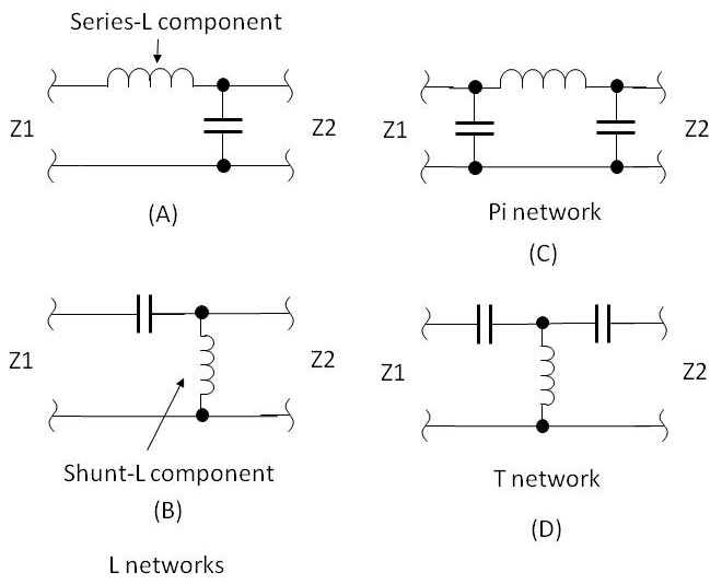
A: There are several basic LC topologies in wide use; all are electrically simple, and each is named for the letter it resembles and the arrangement of the reactive components (Figure 5). For example, the circuit at A is a series-L shunt-C network.
However, their physical realization can range from tiny and placed on a PC board to large in separate chassis or rack as needed to handle larger amounts of power (Figure 6) and (Figure 7).

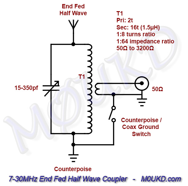
Some of these constructions used fixed inductors and capacitors (the inductors and sometimes even capacitors of the higher-power ones are often “homemade”) and are designed for a single band or frequency; others use adjustable passive components to allow fine-tuning for other bands or to compensate for inevitable parasitics. Many of the homemade units also include a built-in VSWR meter to facilitate optimal tuning for lowest VSWR. Some even add a closed-loop arrangement for controlling a motor which automatically adjusts the large capacitor or inductor to achieve minimum VSWR.
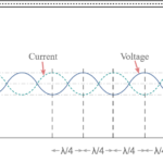
Q: How does the quarter-wave transmission-line matching work?
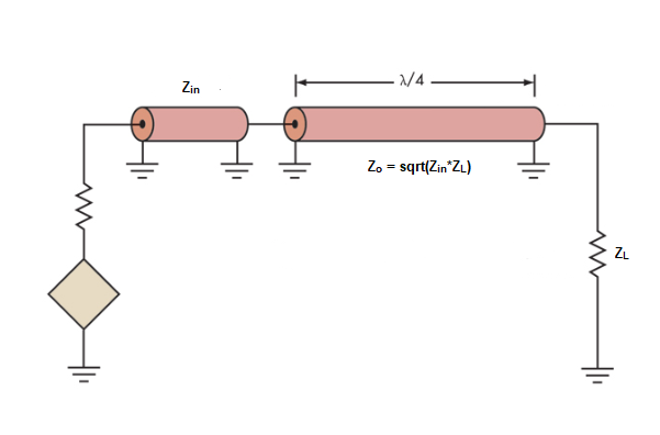
A: Often written out as lambda/4 or λ/4 matching, this uses a quarter wavelength of transmission line transformer to match Zin and ZL impedances. It is simple and requires a series transmission line that is ¼ λ long at the operating frequency, with a characteristic impedance of Zo=√(Zin × ZL) between the two impedances (Figure 8). In some cases, a custom cable or transmission line is needed to provide the or λ/4 matching characteristic impedance if a standard one is not available.
This matching approach can handle high RF power levels, limited only by the rating of the transmission line, and is efficient with low insertion loss. The major drawback is that it can only provide good matching over about an octave bandwidth around the center frequency, but that is not a limitation in many applications.
Q: How do you know what the source and load impedances are to determine the needed matching circuit?
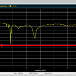
A: There are several ways. For components such as amplifiers, vendors provide input and output impedance values for their devices, along with S-parameters and/or a Smith chart. If this is not available or inadequate, a vector network analyzer (VNA) can be used to measure the needed values at the frequencies of interest.
To then determine the needed matching-circuit values, the designer can use a program which does the calculations or use the Smith chart (again) to determine the possible L and C combinations which are viable options. In most cases, there is no single right answer to implementing a given needed impedance match, but different combinations of Ls and Cs produce the same result. The designer’s challenge is then to decide which of these value combinations are easiest or best to choose with respect to size, cost, tolerance, and temperature coefficients.
Thus far, we have looked at four long-standing and widely used approaches to impedance matching. The next section will look at an approach which is only possible due to modern materials, modeling/simulation, and PC board manufacturing technologies.
Related EE World Content
What are the functions and principles of S-parameters (Part 1)?
What are the applications and measurements of S-parameters? (Part 2)
RF power amplifier, Part 1: Functions and Elements
Solar cells and power, Part 2 – power extraction
Measuring antenna properties
Using the Smith chart for Impedance matching, Part 1
Impedance matching and the Smith Chart, Part 2
The difference between SWR and TDR meters
Measure power in complex RF signals
What are RF waveguides? Part 1: context and principles
What are RF waveguides? Part 2: implementation and components
References
- Wikipedia, “Maximum power transfer theory”
- Tutorials Point, “Maximum Power Transfer Theorem”
- Microwaves 101, “Why Fifty Ohms?”
- Belden, “50 Ohms: The Forgotten Impedance”
- High Frequency Electronics, “There’s Nothing Magic About 50 Ohms”
- Wilson Amplifiers, “50 Ohm vs. 75 Ohm: Which is Best For You?”
- Wikipedia, “Standing wave ratio”
- Antenna-Theory, “VSWR (Voltage Standing Wave Ratio)”
- Electronics Notes, “What is VSWR: Voltage Standing Wave Ratio”
- Electronics Notes, “How to Measure VSWR: approaches & test instruments”
- Maxim Integrated Products, “Glossary Definition for impedance-matching”
- Maxim Integrated Products, “Glossary Definition for VSWR”
- Nuts and Volts, “Impedance Matching”
- Mini-Circuits, “Impedance Matching Devices”
- Mini-Circuits, “Demystifying Transformers: Baluns and Ununs”
- NI (National Instruments), “Impedance and Impedance Matching”
- Tektronix, “Introduction to VNA Basics”
- Triad Magnetics. “Understanding the Maximum Power Theorem”
- QSL Net, “50 MHz (6 Meter) Tuner Circuits”
- QSL Net, “Six Meter Transmatch (Tuner)”
- M0UKD (Amateur Radio Personal Site), “End Fed Half Wave Antenna Coupler (EFHW)”
- Altium Limited, “Stripline vs Microstrip: PCB Routing Differences and Guidelines”
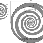
- Researchgate, “A Self-Complementary 1.2 to 40 GHz Spiral Antenna with Impedance Matching”