MEMS relays (also called MEMS switches) have high isolation when open and very low insertion loss or resistance when closed; they can handle signals from DC to multi-GHz, operate with very little power, and their micrometer size means that many can be packed into a small space. These attributes make MEMS relays well-suited for 5G telephony, general RF, medical, and test and measurement systems. They are also finding increasing use of smart energy devices in residential and industrial settings. This FAQ begins with an overview of the two most common MEMS relay constructions, cantilever beam, and air bridge structures, followed by several real-world examples of these devices.
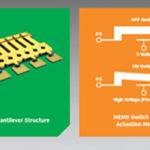
Electrostatic cantilever beam MEMS switches are analogous to conventional electromechanical relays but on a micrometer scale. They can also be compared with a semiconductor switching device with a source, gate, and drain (Figure 1). In an OFF condition, the cantilever beam is not deflected, and the circuit is open. With sufficient voltage applied to the gate, an electrostatic force is developed that pulls the beam down into contact with the drain, turning the device ON and closing the circuit. By adjusting the amount of upward force exerted by the ‘”spring”, the amount of electrostatic force needed to turn the switch ON can be controlled. To remain ON, the electrostatic force must be maintained. Once the electrostatic force is sufficiently reduced, the beam springs back to the horizontal position, and the switch turns OFF. Within limits, the faster the gate voltage can be switched on and off, the faster the switching action. In addition, since the switching is controlled using electrostatic force, the power consumption is low.

Capacitive MEMS switches
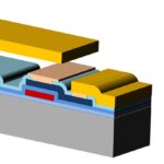
Capacitive MEMS switches use an air bridge structure. When an electrostatic force is applied to the signal or control line, the bridge is pulled down and contacts the conductive dielectric layer on top of the signal line, and the switch is ON (Figures 2a and 2b). If the electrostatic force is maintained, the switch stays ON. Mechanical and electrical factors like fatigue, creep, impact force, and dielectric charging impact the reliability of these switches. Impact force can be especially problematic. The impact force can be very high, resulting in beam failure over time. Improved materials are one possible solution to lengthen operating lives. In practical designs, there’s a trade-off between fast switching times, also referred to as pull-in times, and the resulting increase in the impact force. Various methods have been developed to maintain fast pull-in times and minimize the impact force, such as shaping the drive pulse or using a constant current drive pulse. While these techniques effectively reduce the impact force, they also increase the pull-in time. For example, constant current drive can reduce impact force by up to 80% but results in about a 180% increase in pull-in time. A recently developed structure uses support pillars on either side of the signal line to buffer or cushion the beam during pull-in. Adding the support pillars reduced the impact by 40% while maintaining the same pull in times (Figures 2c and 2d).

Capacitive MEMS switches provide good isolation, low insertion loss, low power consumption, and high-power handling. They require a relatively high activation voltage, and the switching times can be relatively slow, in the microsecond range to turn ON and several hundred nanoseconds to turn OFF. Overall, the performance of these switches is well-matched to several RF and microwave signal applications.
RF applications
RF MEMS switches are used in aerospace, mobile military radios, radar, 5G infrastructure, smartphones, and other applications. Examples include:
- Antenna tuning and impedance matching to maximize power transfer in smartphones.
- We are reducing insertion losses and improving isolation across the RF front end in smartphones and other 5G devices.
- Antenna beam forming is implemented with RF MEMS switches that can electronically control phase shifting and steer RF beam lobes for maximum performance.
- Low-loss tunable filters can function across a broad RF spectrum and are used in software defined radios deployed by the military.
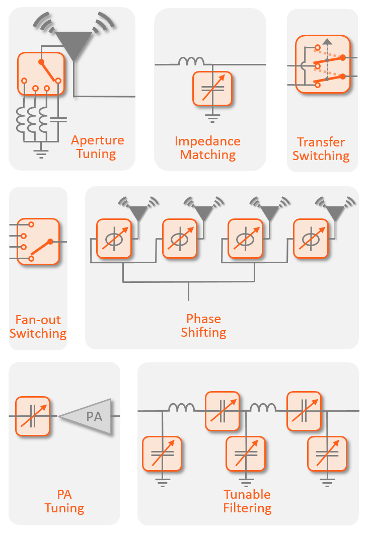
Examples of RF signal chain functions that can benefit from using RF MEMS switches include (Figure 3):
- Antenna aperture tuning
- Antenna impedance matching
- Transfer, or diversity, switching
- Band filter fan-in and fan-out switching
- Phase shifting in antenna arrays
- Power amplifier tuning
- Tunable filtering
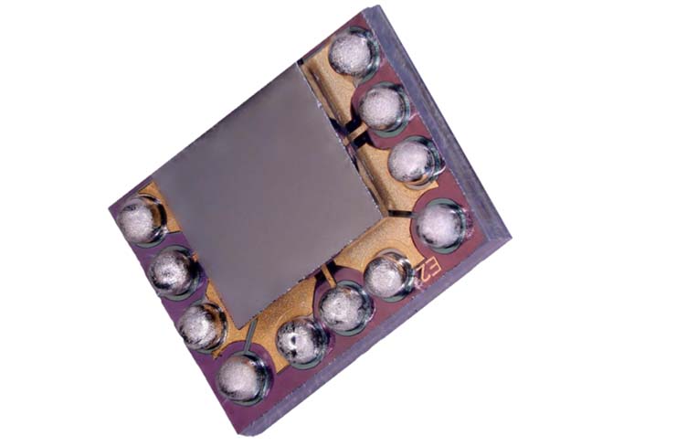
DC to 40 GHz SPDT switch
A low insertion loss (1.6 dB at 40 GHz) DC to 40 GHz single pole double throw (SPDT) MEMS switch with > 32 dB isolation at 40 GHz has been developed that is packaged in a 1.6 x 2.1 mm flip chip configuration (Figure 4). Performance includes:
- Signal integrity preservation. This MEMS relay has a high level of linearity when driving multi-tone signals (input third-order intercept point (IIP3) > 60 dBm) and shows insignificant parasitics with a video-feedthrough < 1 mV.
- Power consumption. Consumes < 100 µW while moving and < 0.5 µW when static, an improvement > 1000X compared to mechanical relays.
- Speed. Once the control voltage is applied, it takes a few ms for the switch to turn ON. When the control voltage is removed, it takes several hundreds of nanoseconds to turn OFF. That performance is over 1000X faster than a typical electromechanical relay.
- Reliability. These MEMS relays’ very small size and light weight make them insensitive to vibration or temperature. The hermetic wafer-level package provides immunity to humidity. The structure is relatively insensitive to mechanical wear and is rated for 1000X more switching operations than a conventional electromechanical relay.
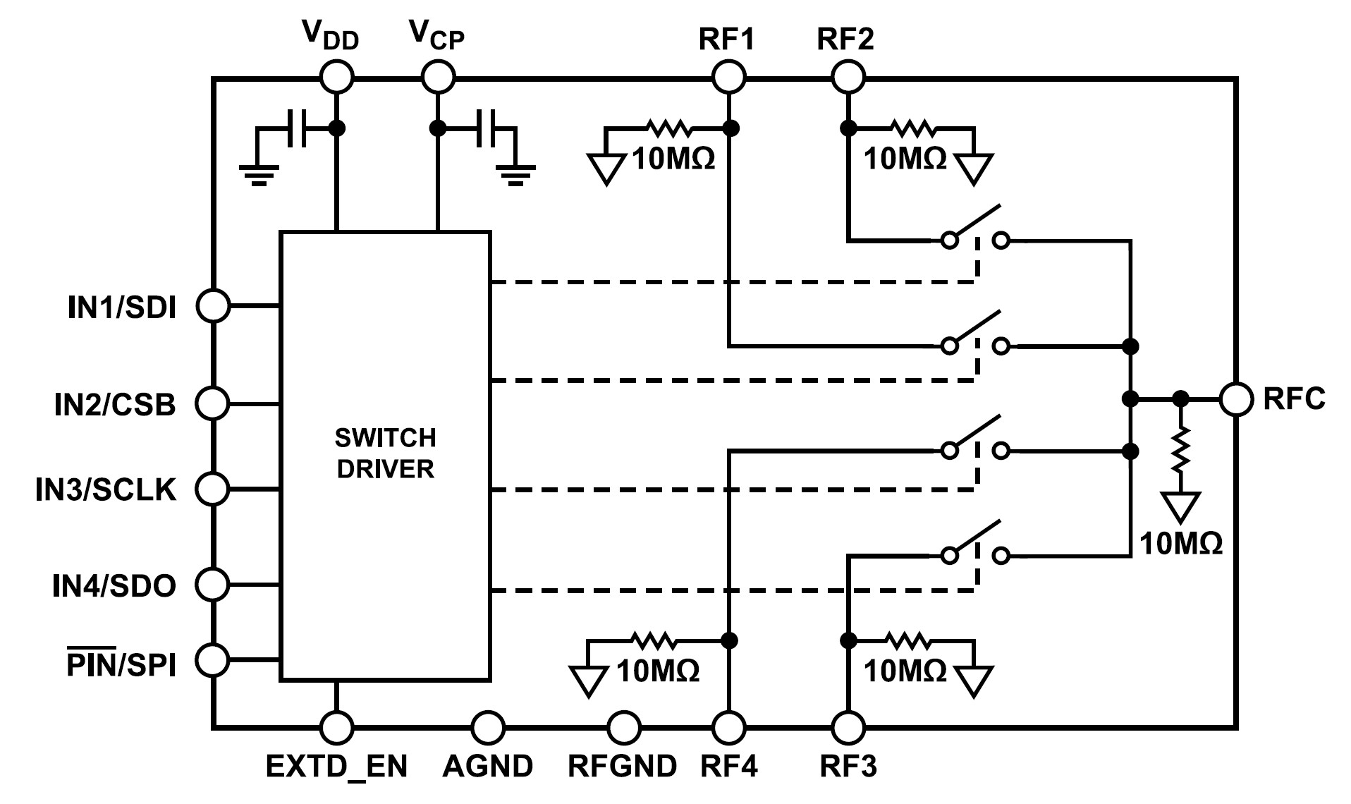
Copackaged switch and driver for RF and precision instrumentation
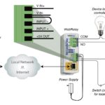
Another example of MEMS switch technology is a single pole four throw (SP4T) electrostatic switch co-packaged with a driver IC that generates the high voltage signals needed to control the switch (Figure 4). The driver IC operates from 3.3 Vdc and can be controlled through a CMOS)/low voltage transistor to transistor logic (LVTTL)-compliant parallel interface or using a serial peripheral interface (SPI). Multiple SP4T switches can be daisy-chained to support more complex switching needs. Representative specifications include:
- DC to 18 GHz operation
- -1.7 dB insertion loss at 16 GHz
- -18 dB isolation at 6 GHz
- 73 dBm IIP3
- 33 dBm RF power
- 9 Ω on resistance
- 200 mA DC current handling
- 200 million cycle lifetime
Power switching
Electrostatic MEMS switches can also replace electromechanical and solid-state relays in power-handling applications. These MEMS switches are fabricated using an array of 50 μm by 50 μm cells. The MEMS switches can be connected in series or parallel to support specific applications. For example, an array with over 400 cells can handle up to 10 A. Three of those arrays have been co-packaged with drive and power monitoring circuitry for smart control and energy management in a smart relay that can handle over 1 kW of power (Figure 5).
These MEMS switches have linear performance from DC to 50 GHz and can switch in less than 10 μs. Other specifications include:
- > 85 dBm IIP3
- < 10mW power consumption
- < 30 mΩ on resistance
- 2 dB insertion loss
- Rated for 3 billion switching cycles
Summary
MEMS switches are used across the RF signal chain in various instrumentation, test and measurement, and power switching applications. They provide high isolation, high linearity, and low power operation. Their small size and light weight contribute to their ruggedness and enable them to support very small solution sizes.
References
Airmems micro-relay, a mems core technology, AirMems
Application Overview, Qorvo
Design and Analysis of the Capacitive RF MEMS Switches with Support Pillars, MDPI sensors
RF MEMS Switches: Understanding their Operation, Advantages, and Future, Conventor
The Fundamentals of Analog Devices’ Revolutionary MEMS Switch Technology, Analog Devices