Standard filters reflect unwanted stopband energy, but reflectionless filters present a seamless impedance across both stopband and passband, which greatly improves performance of the RF signal chain.
Beginning in 2011, Dr. Matthew A. Morgan of the National Radio Astronomy Observatory (NRAO) in Charlottesville, West Virginia, working with Tod A. Boyd and later with Wavley M. Groves III, devised the equations and approach to building reflectionless filters. The need was driven, in large part, by the radio-telescope work at NRAO, where the need for large dish antennas and supercooled low-noise amplifiers also demands the best in filters. Every improvement which minimizes aggravating the poor SNR and low absolute signal level, which degrade the analog signal chain, is worth an attempt. (Morgan has obtained patents on the concept and design.)
When it comes to filters, mathematical analysis is a critical first step. Depending on your perspective, this analysis is boring, impenetrable, fascinating, essential, or better done by someone else (pick one or more choices). This article will not attempt to repeat the math or analyze the filter concepts: there’s no need to do the former, and it is tough to summarize the latter. The details of the reflectionless filter analysis are presented by the innovators in the References.
What we can do, however, is look at the schematic and performance of a typical reflectionless filter. While theoretical filter design and simulation is a topic of countless graduate papers (think of it as the EE analog to James Joyce’s Ulysses), the work of Morgan and associates has been built and tested, and are components are commercially available (more on that later).
The theory has even gone a step further toward making it more suitable for these implementations. By some further insight and analysis and some clever non-intuitive steps of splitting the first inductor into two series inductors and the last capacitor into two parallel capacitors, the final low-pass filter topology has all equal-value inductors, capacitors, and resistors.
This also simplifies the design when selecting the filter pole frequencies (similar results obtained for the high-pass, band-pass, and bandstop filters). Figure 1 shows the basic symmetrical component arrangements for the quartet of filter types.
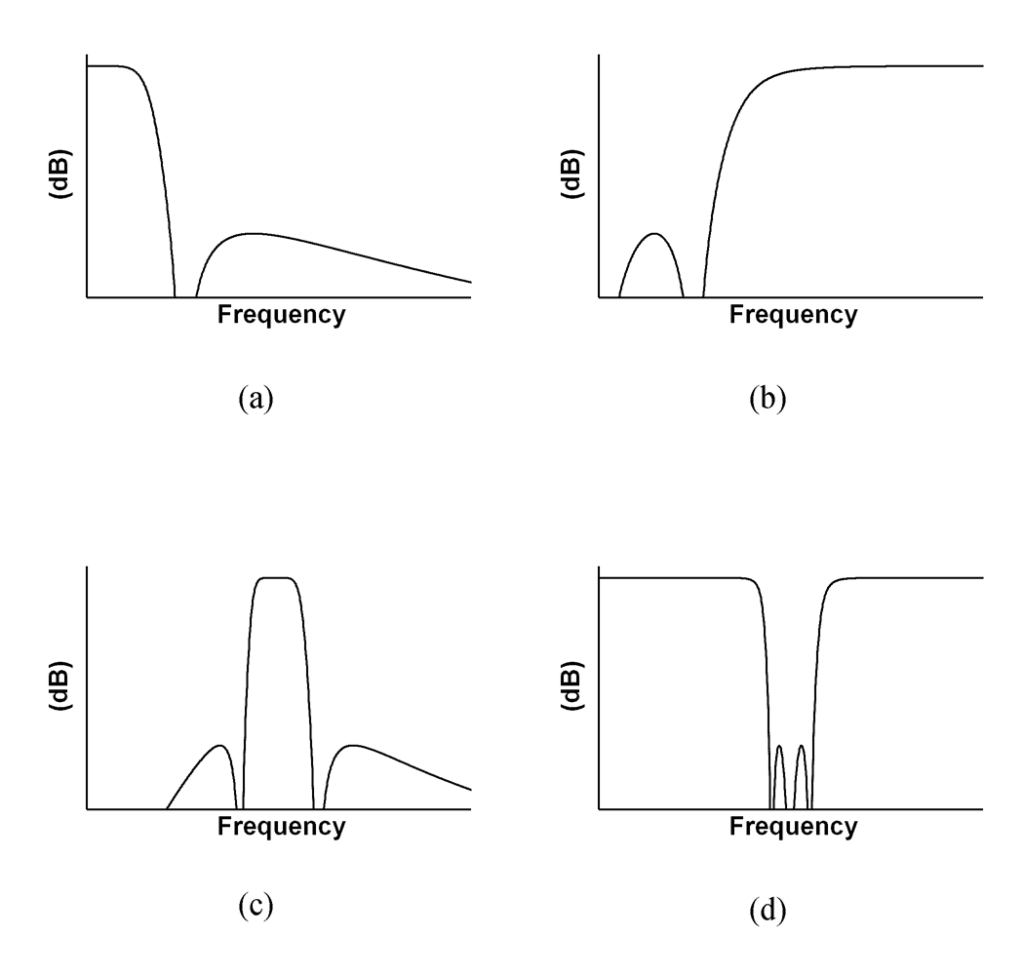
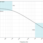
The corresponding attenuation versus frequency of the four arrangements is shown in Figure 2.
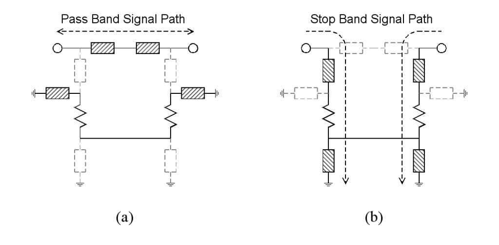
What is actually happening to the signal energy as it passes into and through these filters? Figure 3 shows the signal’s path through the filter in the passband and the stopband.
In this figure, the elements (resistors, inductors, capacitors, and series and shunt combinations) are represented by rectangular impedance elements. The solid rectangles represent relatively low impedances, and the grayed-out elements represent relatively high impedances. When a signal is in the filter’s passband, it passes directly through from one port to the other port. When a signal is in the filter’s stopband, it is blocked from passing between the ports and instead is routed directly to the absorbing resistors in the circuit and then to ground, but it is not reflected.
Another issue is the amount of stopband attenuation available with these filters. At about 14.5 dB, it’s modest and might seem insufficient, as many designs need attenuation in the tens of dB. However, the analysis and real-world tests show that these reflectionless filters can easily be cascaded to achieve higher figures. Since the filter sections are perfectly matched (in theory), there is no inherent difficulty in cascading them. Each section cascaded will provide an additional 14.5 dB of rejection in the stopband. This is unlike conventional filters, where cascading brings all sorts of undesired effects and impairments in performance.
Finally, there’s the issue of filter order. Conventional filters are often synthesized as 1st-, 2nd-, and even 3rd-order topologies for sharper cutoffs, but as with cascading, there are often undesired side effects with respect to factors such as insertion loss. The reflectionless filters can also be synthesized as higher-order filters. Still, while these higher-order filters do result in sharper cutoff characteristics (good), they also develop higher out-of-band peaks (not good), with the stopband peaks at just under -14, -4 dB, and -2 dB for the 1st-, 2nd-, and 3rd-order filters, respectively.
Instead, the desired filter performance can be achieved by simply cascading 1st -order, single-pole filter sections. Each section cascaded will provide an additional 14.5 dB of rejection in the stopband. There’s more to filter-performance assessment than just stopband attenuation and rolloff. The cited papers discuss other important issues, such as the crucial “Q” factor, group delay, and other parameters.
Mini-Circuits introduced off-the-shelf filters using the reflectionless approach in 2015. Part 4 of this article looks at some of these available reflectionless filters.
EE World References
- VSWR and impedance, Part 6: Microstrip and stripline
- VSWR and impedance, Part 5: Making a match
- VSWR and impedance, Part 4: Measurements
- VSWR and impedance, Part 3: Implications
- VSWR and impedance, Part 2: Reflected power
- The basics of VSWR and impedance, Part 1
- What’s all this VNA calibration stuff?
- BAW filters keep RF interference out
- An overview of filters and their parameters, Part 4: Time and phase issues
- An overview of filters and their parameters, Part 3: Key parameters
- An overview of filters and their parameters, Part 2: Basic concepts
- An overview of filters and their parameters, Part 1: Context
- Filters, Part 1: Analog, switched, and digital filters
- Filters, Part 2: SAW and BAW devices for RF
- 5G RF filters need more innovation
External References
- Mini-Circuits, “Reflectionless Filter Basics: A Brief History of the Genesis of Reflectionless Filters”
- Mini-Circuits, “Filtering without Reflections: Flattening Multiplier Chain Conversion Efficiency & More “
- Mini-Circuits, X-Series MMC DC to 21 GHz Reflectionless Filters data sheet
- Matthew Morgan, 2015, “Synthesis of a New Class of Reflectionless Filter Prototypes”
- Morgan, Groves, and Boyd, 2018, “Reflectionless Filter Topologies Supporting Arbitrary Ladder Prototypes”
- Microwaves 101, “Reflectionless filters”
- Microwave Journal, “Reflectionless Filters Improve Linearity and Dynamic Range”
- Matthew Morgan, U.S. Patent 8,392.495 B2 (2013), “Reflectionless filters”
- Matthew Morgan, U.S. Patent 10,277,189 B2(2019),” Transmission line reflectionless filters”

