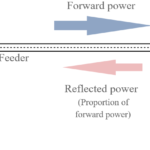
Standard filters reflect unwanted stopband energy, but reflectionless filters present a seamless impedance across both stopband and passband which greatly improves performance of the RF signal chain.
Filters are an area of intense interest, analysis, simulation, and often physical fabrication along with tests and academic papers. Yet, for hands-on design engineers, it’s important to be able to replicate such filters in quantity or buy them as off-the-shelf devices with datasheets and guaranteed specifications.
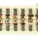
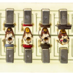
Reflectionless filters are not just an academic construct. They have been mass-produced and sold by Mini-Circuits using a gallium arsenide (GaAs) semiconductor integrated passive device (IPD) fabrication-process technology. Another important benefit of the GaAs IPD process is that the resulting reflectionless filters are also extremely stable over temperature and exhibit a relatively high operating temperature beyond 100⁰C.
Reflectionless filters with frequency response from hundreds of megahertz to over 30 gigahertz have been realized, such as the XBF-282+, a 2350 to 3150 MHz MMIC (monolithic microwave integrated circuit) bandpass filter (Figure 1).
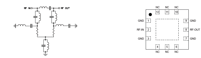
As with any practical filter, additional loss and parasitics do affect performance relative to the ideal filter circuit. Using the GaAs IPD process, the extremely small filters are built with equally compact and planar spiral inductors and capacitors, which have relatively low Q (rolloff sharpness) values, while higher values would be preferred. As a result, the tradeoff when using these extremely compact filters (3×3 mm QFN package) is generally higher insertion loss. However, a benefit of the reflectionless filter topology is that these filters can easily be cascaded, so sharper roll-off and greater stopband rejection are obtainable simply by adding filters as modular building blocks.
This ability allows designers to combine reflectionless filters to achieve the desired response. For example, reflectionless filters may be cascaded to enhance a filter’s stopband attenuation, extend the stopband match, or create ultra-wideband (UWB) filters, as two examples with Mini-Circuits devices show.
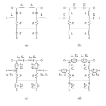
In one example, the stopband attenuation, which is ultimately limited by the fabrication constraints of the GaAs IPD process, can be improved by combining two complementary low-pass reflectionless filters (Figure 2). As another example, a UWB bandpass filter with a good stopband match can be achieved by combining a low-pass and a high-pass reflectionless filter (Figure 3).

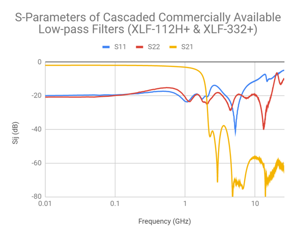
Fig 2: S-Parameters of a single reflectionless low-pass filter versus two cascaded, reflectionless low-pass filters. (Image source: Mini-Circuits (left) (right)
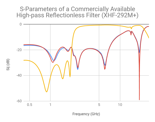
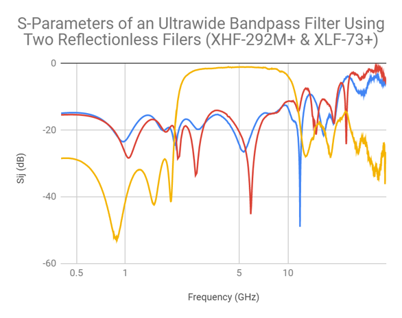
Fig 3: A UWB bandpass filter with a good stopband match can be realized by combining a low-pass and high-pass reflectionless filter. (Image: Mini-Circuits (left) (right)
Conclusion
Reflectionless filters can overcome many of the subtle yet significant design issues, degradations, and signal-integrity impairments associated with using reflective filters into a high-frequency signal chain. These issues are primarily due to the development of standing waves which result from the impedance mismatch in the stopband. As a result, reflectionless filters have become a valuable new tool in the RF/microwave engineer’s toolbox.
EE World References
- VSWR and impedance, Part 6: Microstrip and stripline
- VSWR and impedance, Part 5: Making a match
- VSWR and impedance, Part 4: Measurements
- VSWR and impedance, Part 3: Implications
- VSWR and impedance, Part 2: Reflected power
- The basics of VSWR and impedance, Part 1
- What’s all this VNA calibration stuff?
- BAW filters keep RF interference out
- An overview of filters and their parameters, Part 4: Time and phase issues
- An overview of filters and their parameters, Part 3: Key parameters
- An overview of filters and their parameters, Part 2: Basic concepts
- An overview of filters and their parameters, Part 1: Context
- Filters, Part 1: Analog, switched, and digital filters
- Filters, Part 2: SAW and BAW devices for RF
- 5G RF filters need more innovation
External References
- Mini-Circuits, “Reflectionless Filter Basics: A Brief History of the Genesis of Reflectionless Filters”
- Mini-Circuits, “Filtering without Reflections: Flattening Multiplier Chain Conversion Efficiency & More“
- Mini-Circuits, X-Series MMC DC to 21 GHz Reflectionless Filters data sheet
- Matthew Morgan, 2015,“Synthesis of a New Class of Reflectionless Filter Prototypes”
- Morgan, Groves, and Boyd, 2018, “Reflectionless Filter Topologies Supporting Arbitrary Ladder Prototypes”
- Microwaves 101, “Reflectionless filters”
- Microwave Journal, “Reflectionless Filters Improve Linearity and Dynamic Range”
- Matthew Morgan, U.S. Patent 8,392.495 B2 (2013), “Reflectionless filters”
- Matthew Morgan, U.S. Patent 10,277,189 B2(2019), ”Transmission line reflectionless filters”