Radio frequency (RF) inductors have several uses and are available in various construction types to suit the performance needs of specific applications. Matching, resonators, and chokes are common uses for inductors in RF circuits. Matching involves eliminating impedance mismatches and minimizing reflection and losses in the lines between circuit blocks such as the antenna and the radio frequency block or intermediate frequency (IF) block. Resonance is used in synthesizers and oscillation circuits to tune the circuit and set the required frequency.
When used as a choke, an inductor can be placed in the power supply lines of functional elements such as the RF block or the IF block to attenuate high-frequency ac currents. Bias tees allow a DC current to bias an active device such as a diode. The DC bias current and the AC/RF signal get added together and come out of the AC+DC output port.

RF inductor specifications
Inductance is the characteristic of an electrical conductor that opposes a change in the electric current flowing through it. It is defined as the ratio of the induced voltage to the rate of change of current, causing the induced voltage and is measured in Henries (H). Inductance ratings for RF inductors typically range from about 0.5 nanoHenry (nH), or less, to hundreds of nH. As discussed in the section below on RF inductor construction choices, inductance is dependent on construction, core size, core material, and the number of coil turns. Inductors are available with either fixed or variable inductance values.
DC current rating is (DCR) related to the DC resistance and is measured in amps. DCR determines the amount of current the inductor can handle without overheating or saturating. This is an important specification when considering the thermal performance of an inductor. Power loss increases with current and DC resistance, causing an increase in the inductor’s temperature. Inductors are typically rated for a specific ambient temperature, and a temperature rise above ambient due to current through the inductor. For example, a part rated for 125°C ambient and a 15°C rise due to the full current rating (Irms or Idc) will have approximately a 140°C maximum part temperature.
Saturation current is the DC current, which causes the inductance to drop by a specified value. The inductance drops because the core can only contain a certain amount of magnetic flux density. Saturation current is related to the magnetic properties of the inductor. DCR is related to physical properties, and it describes the maximum DC current that can be passed in an inductor.
Self-resonant frequency (SRF) is defined as the frequency beyond which the device stops working as an inductor. Inductors have low distributed capacitance between terminal electrodes or the turns of a wire-wound conductor, and the device’s inductance resonates with that distributed capacitance at the SRF. At the SRF, the inductor acts as a resistor with impedance. At higher frequencies, the distributed capacitance becomes dominant.
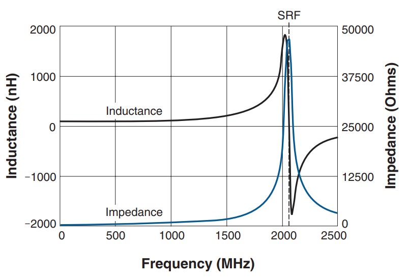
When selecting an inductor for high-frequency circuits and modules, it is not enough to simply consider the required inductance; the SRF should be at least 10X higher than the operating frequency. For choke applications, the SRF is the frequency where the impedance is at its maximum, and that provides the best signal blocking.
Q factor is a dimensionless parameter that describes how underdamped an oscillator or resonator is. It is approximately defined as the ratio of the initial energy stored in the resonator to the energy lost in one radian of the cycle of oscillation. Q factor is alternatively defined as the ratio of a resonator’s center frequency to its bandwidth when subject to an oscillating driving force.
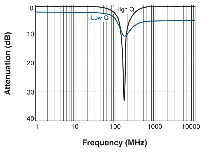
A high Q value results in a narrow bandwidth, which is important if the inductor is used as part of an LC tank (oscillator) circuit or in narrow bandpass applications. High Q also leads to low insertion loss, minimizing power consumption. All frequency-dependent real and imaginary losses are included in Q’s measurement, including inductance, capacitance, skin effect of the conductor, and core losses from the magnetic material.
Specification tradeoffs
Physical RF inductors are non-ideal devices and include parasitic resistances, inductances, and capacitances, which are non-linear and complex effects that compromise the performance and result in the need to make tradeoffs between the various performance specifications. Some examples include:
Higher current requires larger wire or more strands of the same wire size to keep losses and temperature rise to a minimum. Larger wire lowers the DCR and increases the Q, but at the expense of larger part size and possibly lower SRF. In terms of current ratings, wirewound inductors are superior to multilayer inductors of the same size and inductance value. And wirewound inductors have much higher Q values than multilayer inductors of the same size and inductance.
Higher current capacity and lower DCR can be achieved by using a ferrite core inductor with a lower turn count. However, Ferrite may introduce new limitations such as larger variation of inductance with temperature, looser tolerances, lower Q, and reduced saturation current ratings. Ferrite inductors with open magnetic structures will not saturate, even at full rated current.
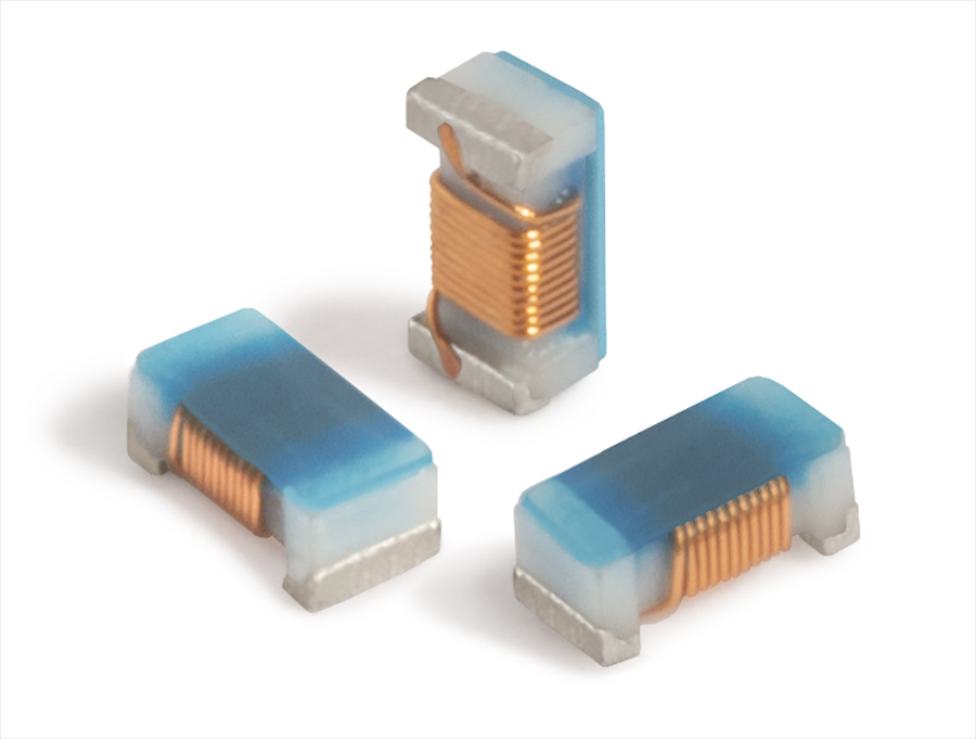
RF inductor construction choices
Several fabrication methods have been developed to mitigate the impact of the various parasitics and optimize RF inductor characteristics for specific applications’ needs.
- Ceramic core chip inductors are for narrow-band filtering in RF and microwave frequency communications devices. They offer very high Qand exceptionally tight inductance tolerances – down to 1%.
- Ferrite or iron core chip inductors are wirewound RF chokes that provide isolation and broadband filtering without core saturation. They offer the highest inductance and lowest DCR in a given EIA size.
- Multilayer chip inductors can provide low DCR, high Q, and high-temperature operation. The ceramic material structure enables high performance at high frequencies, and the multilayer process can provide a wide range of inductance values. Multilayer devices can offer a broader inductance range than thin-film or air-core versions but cannot match the inductance range or current rating of wirewounds.
- Air core inductors are wirewound RF chokes provide isolation and broadband filtering without core saturation. They offer the highest inductance and lowest DCR in a given EIA size.
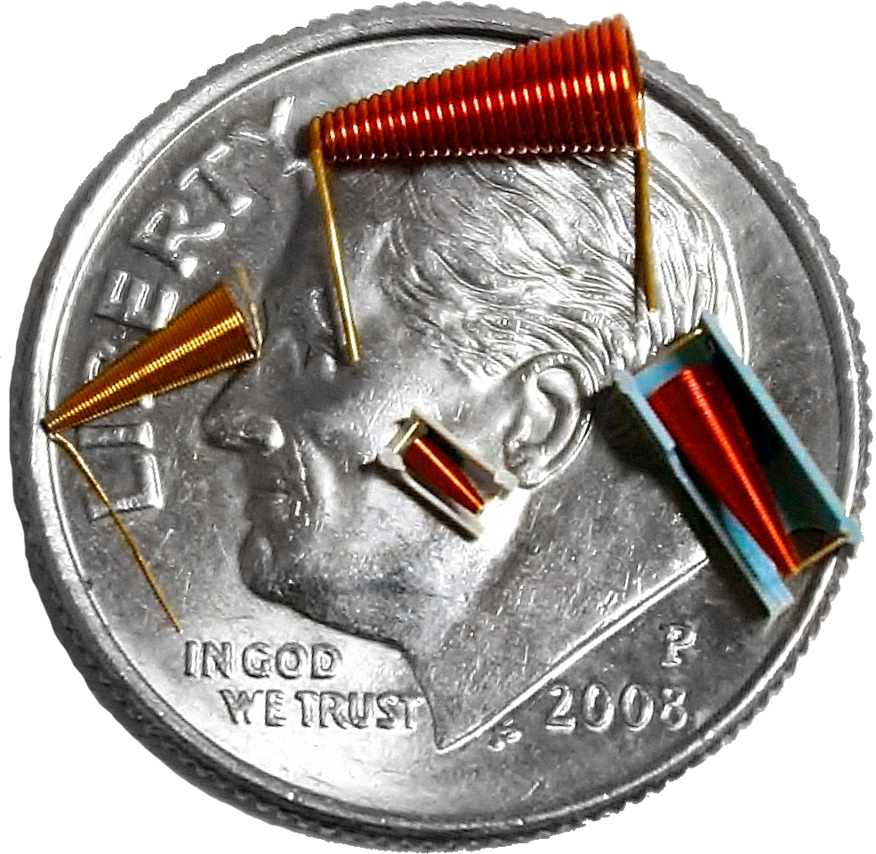
- Conical and broadband inductors have high impedance over a wide bandwidth and are usually offered in a flying lead or surface mount package. Conical inductors are suited for ultra-broadband bias tees up to 100GHz. A single conical is capable of replacing several narrow band inductors cascaded in broadband bias applications.
- RFID and NFC transponder inductors are specialty devices that offer high sensitivity and long read distance in transponder tags and NFC/RFID antennas. They can be optimized for applications such as tire pressure monitoring that demand high performance in harsh mechanical environments and high operating temperatures.
Inductors are an important component in the RF/microwave signal chain. Correctly specifying them can be complex and requires an understanding of the various performance tradeoffs. And once a specification has been developed, numerous construction options must be sorted through before arriving at the best component for a specific application.
References:
Inductor, Wikipedia
Key Parameters for Selecting RF Inductors, Coilcraft
RF inductors, Murata