Waveguides confine and covey electromagnetic energy in the GHz+ range, just as coaxial cables do; they offer lower loss and other virtues, but at a cost in parts and ease of use.
Waveguides (sometimes spelled out as wave guides) do not have the visibility or convenience of coaxial cables but they are an essential passive component in many RF/microwave systems. This FAQ will review their application, forms, and attributes, with no math and just a little physics.
Q: What is a waveguide, in the general sense?
A: A waveguide is any enclosure which confines and conveys energy — electromagnetic (EM) energy or other — from one point to another.
Q: Any kind of energy?
A: Strictly speaking, yes. A rubber hose is a waveguide for flowing water and the energy it transfers. There are also waveguides which do the same for audio energy, such as the Bose Wave Radio. An optical fiber (“light pipe”) is not just a piece of plastic or glass which holds light; it is a waveguide for electromagnetic energy in the optical portion of the EM spectrum. PC board microstrip and stripline structures are also EM-energy waveguides.
Q: But that is not what we mean by a waveguide here, is it?
A: No, we’ll restrict our discussion to waveguides which handle EM energy, starting at around 1 GHz. For EM energy, there are two types of waveguides: the coaxial cable and the older, classic waveguide which is still in use.
Q: I am, of course, familiar with the coaxial cable – that’s a waveguide, too?
A: Yes, it has a solid center conductor surrounded fully by an enveloping shield. Together, they function to support the propagation of RF energy while confining it to the desired path. But when RF engineers use the term waveguides, they generally do not mean coaxial cable, as a coaxial cable is more like a transmission line.
Q: So what does that other, non-coaxial cable waveguided look like?
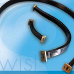
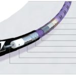
A: The classic waveguide is a metal tube, usually with a rectangular cross-section, which can range in length from a few centimeters to many meters (Figure 1). The length and width of the rectangle sides are a function of the frequency (lower frequency = larger dimensions), with waveguides in common use range from a fraction of a centimeter to several centimeters across both length and width.

While waveguides are usually conductive metal enclosures, it is possible to build waveguides using dielectric surfaces to confine the RF wave energy, but they are rarely used now for various reasons. However, in a well-known example, dielectrics (glass and plastic) are used to create total internal reflection for the light “trapped” in an optical fiber via the step-change in its refractive index — and light is also an EM wave governed by Maxwell’s equations, of course.)
In earlier times, engineers and technicians who worked with waveguides were often called “plumbers;” this could a derogatory or endearing term. They often did the basic sheet-metal work of cutting and soldering the needed waveguides, as standard ones did not exist or would take time to order, fabricate, and deliver!
Q: Why do you even need a waveguide when you have convenient coaxial cable which can carry RF?
A: Coaxial cables are widely used, effective, and essential for many of today’s RF/microwave systems. However, they have increasing power losses as frequency increases. Also, as frequencies increase, the coaxial cables get thinner (some are just a few millimeters in diameter) and so their power-handling capability also is reduced due to possible flashover between the center conductor and outer shield. Further, self-heating of coaxial cables due to inherent, unavoidable losses affects the consistency of their performance and degrades many of their key specifications.
Q: At what frequencies do you begin to need to use waveguides?
A: It depends on the combination of frequency and power. In general, waveguides begin to be useful between around 1 GHz and operate several hundred GHz (beyond that, you are in terahertz region, between the RF and optical parts of the spectrum). Of course, modern coaxial cables also operate into the tens of GHz, are easier to work with than waveguides, and are viable at lower power levels (milliwatts to a few watts, maximum).
However, waveguides are sometimes required even at sub-GHz frequencies in the tens or hundreds of MHz if the power levels are high. For example, an FM-band broadcast transmitter (88-108 MHz) pumping thousands of watts to its antenna may use them. Standard, off-the-shelf waveguides are available from many sources starting at around 1 GHz and going up to around 100 GHz.
Waveguides were also used extensively before the development of our modern, high-performance coaxial cables. Keep in mind that despite their simple appearance, modern coaxial cables are highly engineered, precisely manufactured assembles of center conductor, interposed dielectric, outer shield, and protective insulation demanding high levels of material and production consistency. Cables for higher frequencies with lower loss and better stability are relatively new developments. The first magnetrons in WWII operated in the 500-MHz range (we now consider that a low frequency, but it was very new territory at the time), and used waveguides, as coaxial cables for that frequency did not exist.
Q: When were waveguides developed?
A: Waveguides were independently developed in the early 1930s by researchers at MIT and Bell Labs, as frequencies moved up into the tens and hundreds of MHz and power levels increased to hundreds of watts and even kW levels.
Q: What is the theory of waveguides?
A: Not surprisingly, it is complicated, requiring advanced math, differential equations and, of course, Maxwell’s equations. In simplest terms, a waveguide supports various modes of energy propagation based on its dimensions and length/width ratio. In brief, electromagnetic-energy waveguides are analyzed by solving Maxwell’s equations in some form, using electromagnetic wave equation with boundary conditions determined by the properties of the guide materials and their interfaces. Waveguide principles center on three attributes of the E-fields (electric) and H-fields (magnetic) of EM energy:
- Electromagnetic waves cannot pass through conductors, but are reflected by conductors;
- Any E-field lines that touch a conductor must be perpendicular to that conductor;
- Any H-field lines that are close to a conductor must be parallel to that conductor.
Q: So how does that relate to energy propagation within a waveguide?
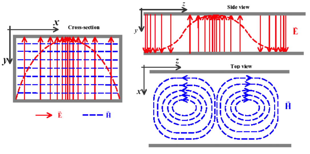
A: As a consequence of these rules, only certain modes of propagation exist. Discussions about the different types of waveguide modes often indicate the specific transverse electric (TE) and transverse magnetic TM modes with integers after them: TEm,n. The numerals M and N can take on separate values from 0 or 1 to infinity. These indicate the wave modes within the waveguide. What is designated as dominant transverse electric mode 10 or TE10 (the mode with the lowest cutoff frequency) is the basic mode of energy propagation in a rectangular waveguide. In that mode, the electric field lines do cross the transverse plane, and they are all vertical (Figure 2). At the same time, the H- field lines are circular and “encapsulate” the crests of the E-field. In other words, the E-field lines are normal (at right angles) to the longer waveguide wall while the H-field lines are normal to the short wall.
Q: What are waveguide modes? Please explain further.
A: Modes in waveguides are classified as follows:
- Transverse electromagnetic (TEM) modes: Neither electric nor magnetic field in the direction of propagation.
- Transverse electric (TE) modes: there is no electric field in the direction of propagation; this is sometimes called H mode because there is only a magnetic field along the direction of propagation.
- Transverse magnetic (TM) modes: there is no magnetic field in the direction of propagation, this is sometimes called E mode because there is only an electric field along the direction of propagation.
There’s much, much more that can be said both qualitatively and qualitatively about the theory of EM energy prorogation in waveguides, but this is a good place to stop!
Q: I am familiar with transmission lines; how does a waveguide differ from a transmission line?
A: A transmission line is a two-conductor structure that can support a TEM wave, while a waveguide is a one-conductor structure than can support a TE wave or TM wave, but not a TEM wave. Again, it’s complicated!
Q: Why are most waveguides rectangular? What about circular ones?
A: Circular ones can be used but they are less common. Perhaps surprisingly, despite their axial cross-sectional symmetry, their EM analysis using Maxwell’s equations is more complicated than it is for rectangular waveguides. For circular waveguides, the dominant mode of energy propagation is the TE11 mode.
Q: What are the dimensions of a waveguide?
A: Again, it’s a function of frequency and mode. There are some guidelines associated with waveguide modes and dimensions: For rectangular waveguides, the TE10 mode of propagation is the lowest mode that is supported, and the width – the widest internal dimension of the cross-section — determines the lower cut-off frequency and is one-half the wavelength of that frequency. In contrast, the TE20 mode occurs when that width equals one wavelength of the lower cut-off frequency.
Part 1 of this FAQ looked at the basic need for and principles of waveguides. Part 2 will discuss actual waveguides and implementation issues, and well as some other unique aspects.
EE World References
Magnetron, Part 1: Application and operating principles
Magnetron, Part 2: History and future
Passive microwave components, Part 1: isolators and circulators
Passive microwave components, Part 2: couplers and splitters
The difference between metal conductors and waveguides
Ultra-high frequency waveguide antennas handle frequencies to 220 GHz
Millimeter-wave waveguide antennas cover up to 220 GHz
Waveguide-to-waveguide transitions deliver minimal loss and VSWR as low as 1.08:1
Flexible waveguide models deliver VSWR as low as 1.05:1
Basics of waveguides, microwaves, and ovens
External References
Electronics & Technology History Wiki, “Waveguides”
Electronics Notes, “Waveguide Modes: TE, TM, TEM”
Electronics Notes, “Waveguide Types: Dimensions & Sizes”
Wikipedia, “Transverse mode”
Wikipedia, “Waveguide (electromagnetism)” (has wg sizing)
Microwaves101, “Waveguide Primer” (has TE mode diagram)
Bright Hub Engineering, “Basics of RF Waveguide Design”
Tutorials Point, “Microwave Engineering Waveguides”
Pasternack/Infinite Electronics International, “Waveguides”
Pasternack/Infinite Electronics International, “Waveguide Frequencies and Geometries”
Radar Tutorial EU, “Waveguide Basics”
Radar Tutorial EU, “Waveguide Input/Output Methods”