Part 1 of this FAQ looked at the context and the need for waveguides; Part 2 looks at the implementation and available components.
Q: What standard waveguide are available?
A: There are thousands of models, configurations, and options. Most waveguides have flanges so they can be connected to create longer guides, or to provide turns and special waveguide accessories. These interconnected elements and sections must be firmly connected with screws set to a specific torque so there is no EM leakage or impedance discontinuity.
Q: What are some of these waveguide “accessories”?
A: There are all sorts of waveguide add-ons: circulators, isolators, attenuators, splitters, “T” junctions, 90⁰ bends, loads, mixers, and more; it is too extensive to cover here. Each of these comes with flanges to match and connect to the associated waveguide itself.
Q: How are waveguides dimensioned?
A: The industry has standardized on waveguide dimensions to ease (but not guarantee) compatibility and connectivity between units from different suppliers. The WR waveguide system is the EIA designation (Standard US) with the letters WR (for waveguide rectangular) followed by numerals indicating the lowest frequency for which they were designed for use. In the WG waveguide system, with RCSC Designation (Standard UK), the waveguides have WG followed by one or two numerals, e.g., WG10. For example, one vendor’s long list of available waveguides begins with these (Figure 1):
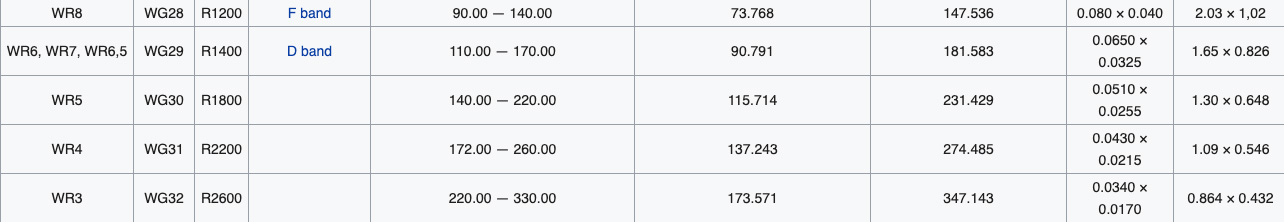
and ends with these, (Figure 2), with dozens of intermediate units:
Note that the WR number corresponds to the internal measurement (in mils, where 1 mil = 0.001 inch) of the wider side of the waveguide.
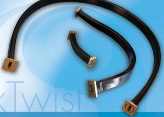
Q: These rigid waveguides seem like a challenge to actually install compared to flexible or semi-rigid coaxial cable; is there an alternative?
A: Yes, flexible waveguides are also available (Figure 3). Some use thinner, ductile, bendable metal (up to a limit, of course!), others use interlocked prices. In general, flexible ones have somewhat reduced performance at a higher cost, but may be the only viable alternative for the installation.
Q: How to you get the microwave energy into a waveguide (or extract the energy from the waveguide) for use in a circuit?
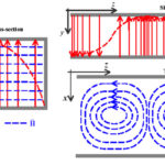
A: In one approach, a small probe or loop is inserted into a waveguide and supplied with microwave energy, and it acts as a quarter-wave antenna. Current flows in the probe and sets up an E field (Figure 4), and the E lines detach themselves from the probe. It can also absorb impinging energy.
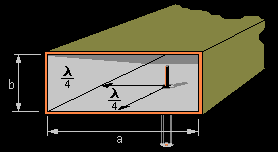
The most efficient place to locate the probe is in the center of the “a” wall, parallel to the “b” wall, and one quarter-wavelength from the shorted end of the waveguide. That is where the E field is maximum in the dominant modem, and therefore the energy transfer (coupling) is maximum at this point. The same arrangement is used to extract energy from the waveguide.
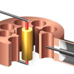
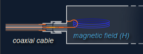
Another way of injecting energy into a waveguide is by setting up an H field in the waveguide, inserting a small loop which carries a high current into (or out of) the waveguide (Figure 5).
The waveguide can also be energized (“fed”) using by a patch or microstrip antenna mounted on the rear wall of the waveguide. In other cases, the waveguide flares out directly into a horn or other antenna.
Q: Are there specialty waveguides?
A: Of course. For example, due to the skin effect at high frequencies, the electric current along the walls penetrates only a few micrometers into the metal of the inner surface. That’s inherent in the functioning of the waveguide since it confines the EM energy flow. The surface, therefore, is where most of the resistive losses occur, so it is vital that the conductivity of the interior surface be as high as possible. For this reason, most waveguide interior surfaces are plated with copper, and some are even coated with silver or gold.
Other specialty waveguides have predrilled access holes or ports so power and energy input/output probes can easily be inserted in the correct place. In some situations, the waveguides may be hermetically sealed and then pressurized with nitrogen gas to reduce the possibility of flashover arcing, thus allowing higher levels of power handling. Conversely, other waveguides may be evacuated and then sealed, such as those in electron-beam systems.
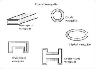
Q: Are waveguides limited to rectangular and round cross-sections?
A: There are other cross-sectional shapes used for specific reasons and some unique advantages, but they are very hard to analyze (Figure 6). In practice, nearly all waveguide installations use the rectangular shape if possible because it has the easiest analysis of the energy-propagation modes and is mechanically the easiest to manipulate. It’s perhaps counterintuitive, but the circular shape — which would appear to be easiest to handle due to rotational symmetry, is difficult to analyze and is very sensitive to mechanical tolerances and imperfections in shape.
Q: In summary, what are the pros and cons of waveguides?
A: As with almost any solution, there are benefits and drawbacks.
Pros of waveguides include:
- very low loss even at multi-GHz frequencies;
- consistent, stable performance once installed;
- ability to handle very high power levels (into kW and even MW range).
Cons of waveguides include:
- higher up-front cost;
- challenges and awkwardness in assembly and routing, and constraints on layout flexibility;
- installation issues, as you just can’t quickly cut one to fit as you would with coaxial cable, or just tuck the excess in the side as you could with coax;
- issues with energy injection and pick-off.
Q: Waveguides seem pretty esoteric and cumbersome, and I don’t think that I will encounter them – is that the case?
A: You already have one: if you have a microwave oven, then you also have a waveguide. A special, single-function waveguide is used to couple the output energy of the microwave’s magnetron into the oven’s cooking area. This leverages an attribute of waveguides: they can be used to feed a horn antenna directly. The magnetron-horn antenna combination is energy efficient, does not leak RF, focuses the RF energy where it is wanted, and minimizes points of connection.
In addition to this major application, there are many RF/microwave situations where coaxial cables can’t provide the needed combination of characteristics for frequency, power rating, RF confinement, and loss, and so waveguides are the only option.
This FAQ has looked at the waveguide, a specialized, often underappreciated, yet vital component of the microwave world. As systems get smaller and frequencies get higher — reaching into the higher tens of GHz — both waveguides and high-end coastal cables will be used, with the decision based on tradeoffs, constraints, mechanical considerations, and performance factors.
EE World References
Magnetron, Part 1: Application and operating principles
Magnetron, Part 2: History and future
Passive microwave components, Part 1: isolators and circulators
Passive microwave components, Part 2: couplers and splitters
The difference between metal conductors and waveguides
Ultra-high frequency waveguide antennas handle frequencies to 220 GHz
Millimeter-wave waveguide antennas cover up to 220 GHz
Waveguide-to-waveguide transitions deliver minimal loss and VSWR as low as 1.08:1
Flexible waveguide models deliver VSWR as low as 1.05:1
Basics of waveguides, microwaves, and ovens
External References
Electronics & Technology History Wiki, “Waveguides”
Electronics Notes, “Waveguide Modes: TE, TM, TEM”
Electronics Notes, “Waveguide Types: Dimensions & Sizes”
Wikipedia, “Transverse mode”
Wikipedia, “Waveguide (electromagnetism)” (has wg sizing)
Microwaves101, “Waveguide Primer” (has TE mode diagram)
Bright Hub Engineering, “Basics of RF Waveguide Design”
Tutorials Point, “Microwave Engineering Waveguides”
Pasternack/Infinite Electronics International, “Waveguides”
Pasternack/Infinite Electronics International, “Waveguide Frequencies and Geometries”
Radar Tutorial EU, “Waveguide Basics”
Radar Tutorial EU, “Waveguide Input/Output Methods”