The four most-common relay technologies include electromechanical relays, reed relays, solid-state relays, and optotriacs. These relay technologies have widely varying capabilities, making them suitable for different applications. This FAQ compares each relay technology’s structures, specs, operations, and applications.
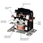
The oldest and most basic type of relay are electromechanical designs. When an input value, usually current or voltage, reaches a set level, the relay switches ON. Yoke designs are common and consist of a soft iron core wrapped with a coil of wire (forming an electromagnet), an armature, a spring to establish the OFF position of the armature, and one or more sets of contacts (Figure 1). Current flowing through the electromagnet causes the armature to move. When the armature moves, the contacts on the end of the armature are opened or closed, depending on the design of the relay. When the electromagnetic is not energized, the spring moves the armature back to its starting position.
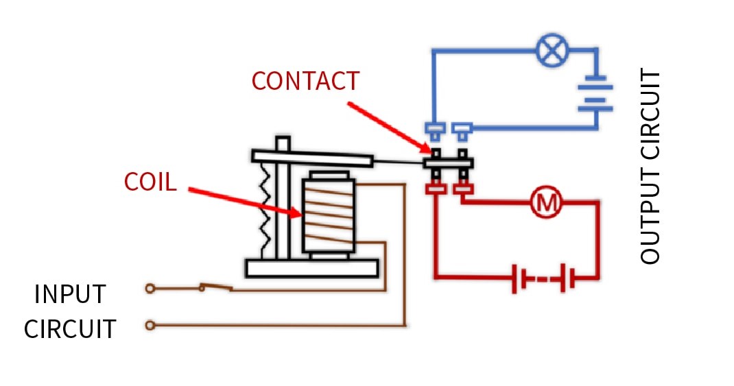
Relays enable a relatively small input value to control a much larger output value. They also provide electrical isolation. Common applications for electromechanical relays include automatic machine operation like temperature, lighting and motor controls, circuit protection, switching signals, radio frequency circuits, and inductive and capacitive circuits. Examples of relay functions include:
- Galvanic isolation between the primary (actuating or control) circuit and the loads.
- Single input with single- or multiple-output configurations
- Separation of dc and ac circuits
- Interface between low-power electronics and high-power loads
- Various control mechanisms like time delay, temperature sensing, and light brightness sensing
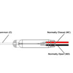
When a contract is open with the relay not activated, it’s referred to as a normally open (NO) contact. Conversely, a contact that is closed when the relay is not activated is referred to as a normally closed (NC) contact. NO contacts in a monostable (non-latching) design are the most common relay configuration. Monostable relays have a single stable condition, OFF, and remain in that position until power is applied to the electromagnet. When the electromagnet is energized, the relay switches and remains in that position until the electromagnet is de-energized. Relay contacts are also classified as:
- “Form A” has NO contacts when the coil is not energized
- “Form B” has NC contacts when the coil is not energized
- “Form C” has three leads, including one NO and one NC circuit. These relays are also called “changeover” since the common contact changes from the NO position to the NC position when the coil is energized.
Bistable (latching) relays remain switched even after the electromagnet is de-energized. To return a bistable relay to its unswitched position, the coil must be counter or reverse, energized. While monostable relays only require power to turn on, bistable relays need to be powered to turn on and off. That difference results in several advantages for bistable designs.
- Monostable relays require power to be continuously applied to remain in the switched position, while bistable relays need zero power to remain switched.
- Since the coil in a bistable relay is not continuously energized, it does not continuously generate heat, and the relay will run cooler and can have a wider current range.
- If a main power source fails, the contacts in a bistable relay will not change state.
Power relays are rated up to 600 V; above that level, the device is often referred to as a contactor (for a discussion of contactors, see the FAQ on “When to use a relay and when to use a contactor”). Power relays generally use larger electromagnets and can be subject to overheating if they are left activated for an extended period. To reduce relay heating, pulse width modulation (PWM) control can be used. Under PWM control, the current in the electromagnet is rapidly turned on and off to reduce the average current and thereby reduce the temperature. This technique is effective since the amount of current needed to maintain a relay in the activated position, called the hold current, is less than the current required to activate the relay initially.
Reed relays
Like conventional electromechanical relays, reed relays, also called reed switches, employ an electromagnet to affect the switching action. And, like electromechanical relays, reed relays can have one or more sets of contacts. Some reed relays have eight or more sets of contacts. Reed relay contacts are typically inside a hollow electromagnet. The contacts are made with a magnetic material, and the electromagnet moves them directly without needing an armature. In a typical design, the contacts are sealed in a class tube that protects them from corrosion, and the tube is placed inside the coil (Figure 2).
The glass envelope can contain multiple reed switches that are actuated simultaneously. Since the components in a reed relay are small and lightweight, they can be switched much faster than armature-based relays. Reed relays use less power to operate and have lower contact capacitances. However, they have limited current handling capability, usually 5 A or less, and are generally used to switch voltages less than 50 Vac, called ‘dry’ switching. With few moving parts, these relays are highly reliable and can be used over extended periods. Both reed and solid-state relays have much longer lifetimes compared to electromechanical relays. When low voltage and low power switching are needed, reed relays provide several performance advantages:
- Billions of lifetime switching operations
- Hermetically sealed construction protects the contacts from dust, corrosion, and debris
- Intrinsically safe and provide reliable operation in hazardous locations
- Low contact resistance, typically less than 50 mΩ
- High insulation rating, typically greater than 1015 Ω
- Switching times from 500 μs to 3 ms
- Capable of switching nanovolt signals
- High-frequency designs can handle up to 7 GHz
These capabilities make reed relays useful in a wide range of applications, like:
- Providing voltage isolation in
- Battery management systems in electric and hybrid vehicles
- Photovoltaic energy systems and power distribution systems
- Medical equipment such as automatic external defibrillators and surgical devices
- High-density switching matrices and multiplexers in test equipment and communications systems
- Intrinsic safety in geothermal, mining, and oil and gas production
MOSFET solid state relays and optotriacs
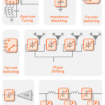
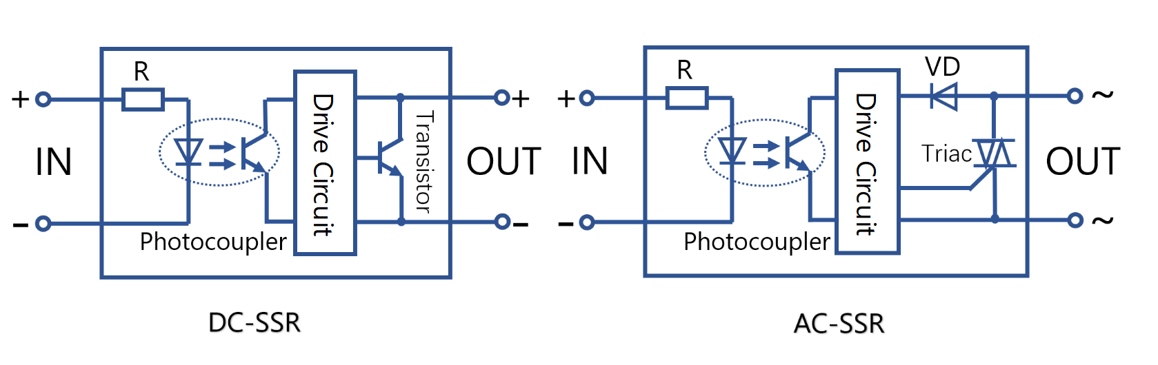
Solid state switches can be built using MOSFETs or triacs. When MOSFETs are used, the devices are typically called solid-state relays (SSRs). When a triac is used as the triggering device, it’s referred to as an optotriac or a phototriac. SSRs are suitable for switching AC and DC loads. In a DC switching SSR, the optically driven MOSFET turns on another higher power MOSFET, and in an AC switching SSR, the optically driven MOSFET is used to turn on a triac (Figure 3).
SSRs combine Low Rdson MOSFETs and low-power CMOS control to provide highly efficient and reliable power switching. SSRs generally cost more than electromechanical relays, but they offer several advantages:
- Higher reliability
- 10X, or more, faster switching speed
- Lower power consumption to initiating switching
- No audible noise from switching actions
- Small size and lightweight
- High electrical insulation and isolation
- Shock and vibration resistance
An optotriac relay combines a phototriac with a power triac (Figure 4). Compared with electromechanical and reed relays that can be used with AC or DC power, optotriac relays are used in applications like lighting dimmers, heaters, and motor drives to control the AC power. The phototriac is a triac with a light-sensitive gate combined with a light-emitting diode (LED). When the sufficient forward current (IFT) flows through the LED, it produces enough photons to turn the turn on and latch the triac. The triac remains on until the current through the triac falls below its holding current, at which time the triac turns off. A detector chip can be added that causes the triac to be turned on only when the AC voltage is close to zero. These “zero-cross” optical triacs have lower surge currents and generate less switching noise than non-zero cross designs. Phase angle switching for load control requires using a non-zero crossing phototriac, also called a “random phase” triac. Zero voltage switching control of the triac can drive a load in continuous mode.

Summary
Electromechanical, reed, and solid-state relays offer varying combinations of power handling, switching speed, reliability, noise generation, and other specifications. Most relay technologies can handle AC and DC loads, but optotriac relays are the exception and are only suited for controlling AC loads.
References
Controlling a Triac with a phototriac, STMicroelectronics
Reed Relay, Wikipedia
Reed Switches used in a Reed Relay Application, Standex Electronics
Types of Relays – Electromechanical Relays (EMRs) and Solid State Relays (SSRs), TE Connectivity
What are the differences between Solid State Relays and Electromechanical Relays (SSR vs. EMR)? Huimu Electronics