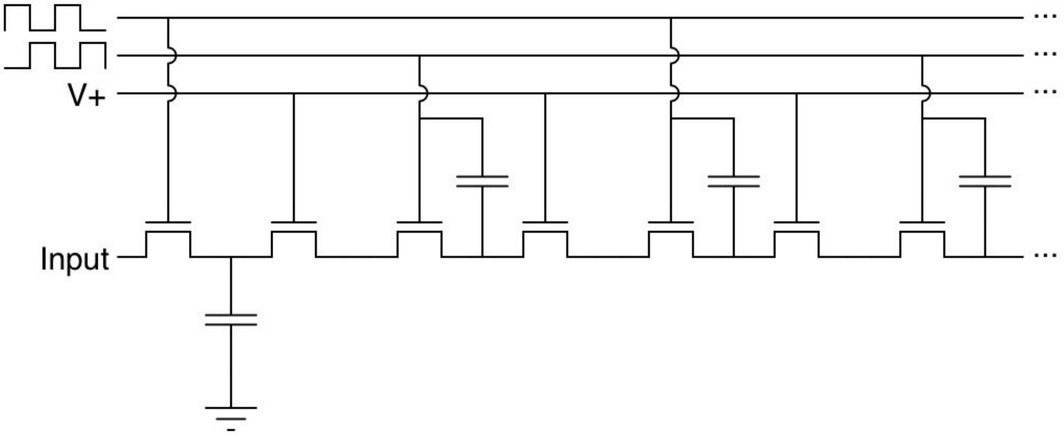
A bucket brigade device (BBD) is a discrete-time analog delay line using capacitors that has been replaced in most digital signal processing applications. But it continues to be used in some specialty applications such as guitar and audio sound effects and some types of sensors. It consists of a series of capacitance sections where a stored analog signal is moved from section to section one step at a time during each clock cycle (Figure 1). It is conceptually similar to a brigade of people passing buckets of water from one to another, hence the name buck brigade device.
This FAQ reviews the broader implications of the technology behind BBDs, looks at basic BBD architectures and practical implementation considerations, and closes by presenting how BBDs are used in guitar sound effects.
As well as being useful in audio effects, a BBD is interesting because of its relationship with other well-known electronics devices. For example, the concept behind the BBD led to the development of charged-coupled devices (CCDs) used in imaging devices. Using capacitors to retain a voltage state is related to dynamic random access memory (DRAM) designs where the charges are refreshed instead of being propagated. Outside of audio special effects, BBDs have mainly been replaced by digital signal processing technologies.
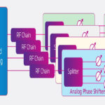
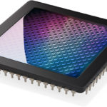
BBDs have been used as an analog beamformer for piezoelectric ultrasonic sensor phased arrays. And CCD-based pixel arrays operate like a BBD, with the light-generated charge from each pixel passing along the entire array of pixels to the corner of the chip, where it is amplified and recorded.
BBD IC first appeared around 1980. The most common BBD uses an antiphase clock configuration (Figure 2). Designs range from 512 stages to over 4,000 stages and can include a single delay line or dual delay lines. Various BBD implementations support clock frequencies from 1.5kHz to 1.5MHz.
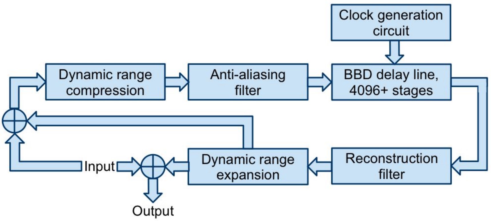
BBD ICs have limited dynamic ranges due to charge transfer inefficiencies and nonlinearities. The input signal level must be a small fraction of the supply voltage to achieve a low total harmonic distortion (THD). A BBD IC has about a 60 dB signal-to-noise ratio (SNR) and a variable insertion gain up to about 2 dB for optimal input levels. The insertion gain and SNR become more problematic as the number of stages increases and are also sensitive to clock frequency. As a result, compensation circuits are essential in applications such as echo effects with large numbers of stages and variable clock frequencies. Compensation circuits are not needed in applications such as choruses, flangers, phasers, and vibratos with less variable clock frequencies and shorter delay times. BBD IC application examples include:
- Echo circuits (Figure 3)
- Thousands of stages
- Highly variable clock frequency
- Anti-aliasing and reconstruction filters used
- Can perform compression or expansion
- Feedback can be included for repeating echos
- Chorus, Flanger, Phasers, and Vibrato
- About 1,000 stages
- Low-frequency oscillator used to vary the clock frequency
- Anti-aliasing and reconstruction filters used
- Feedback is used in some designs
What is the chorus effect?
A chorus effect simulates the subtle timing and pitch differences when multiple musicians or vocalists play the same note but vary slightly in timing and pitch. The sound of chorusing has been described as making a sound seem ‘larger.’ It’s based on a multiplying effect by creating a copy, or multiple copies, of a sound and varying the timing or pitch using a low-frequency oscillator (LFO) with the BBD, then mixing the modulated copies with the original sound. Instead of using a pitch circuit to modulate the pitch, a chorus modulates the delay time of the sound. A constantly changing phase shift is created between the duplicated sound(s) and the original sound. Chorus effects typically use delay times between 15 and 35 ms. Slower delays produce a more subtle chorusing effect, while faster rates cause more phase shifting and pitch modulations.
How do flangers work?
Flangers produce a variation on the chorus effect by creating a copy of the sound and using an LFO to modulate the delay time through the BBD. Flangers use shorter delay times (typically 1 to 5 ms) and only one copy of the original sound. Since choruses use pitch and timing differences, the frequencies of the original sound and the copies are not the same, minimizing interference. With flangers, significant interference occurs since the copied signal is the same as the original. Instead of creating a ‘larger’ sound like a chorus effect, a flanger ‘smears’ the sound. As the two sounds are phase-shifted, the waveforms move from being completely in phase, causing constructive interference, to being completely out of phase, causing destructive interference. The LFO is used to modulate the delay time of the copied sound. As a result, the sound from a flanger has a resonance that sweeps at the rate of the LFO. Flangers also use the feedback of the copied signal to smear the sound further, resulting in harsh, metallic timbres.
How do phasers and vibratos work?
Unlike choruses and flangers, phasers don’t modulate the delay time. Phasers use an LFO to sweep a copied sound against the original sound, but instead of delaying the sound, it’s sent through an all-pass filter. The all-pass filter is used to change the phase relationships of the various frequencies of the copied and original sounds. As the copied sound goes through the all-pass filter, certain frequencies are phase-shifted, and the result is combined with the original sound, forming notches at the frequencies where the all-pass circuit created phase shifts.
A vibrato is a specific form of a phaser. In a phaser, identical capacitor values are used in the phase-shifting stages. In contrast, a vibrato uses stagger capacitor values to create a rapid, slight variation in pitch and a stronger or richer tone.
Summary
BBDs are a mostly obsolete technology that continues to be used in niche applications such as guitar special effects and some sensor systems. The technology behind BBDs can be found in more advanced devices such as CCD imagers and DRAM memories. Like vinal records, BBDs have resisted the encroachment of digital signal processing into the field of audio systems.
References
An Effective Model of Bucket-Brigade Device-Based Audio Circuits, Colin Raffel
Bucket-brigade device, Wikipedia
Bucket Brigade Devices: MN3007, Electrosmash
Practical Modeling of Bucket-Brigade Device Circuits, IEEE International Conference on Digital Audio Effects
Understanding Chorus, Flangers, and Phasers in Audio Production, iZotope