Precoding is the transmitter signal processing needed to affect the received signal’s maximization to specific receivers and antennas while reducing the interference to all other receivers and receiving antennas. Precoding involves preprocessing of the transmit signal in an RF system. As described below, precoding uses channel state information at the transmitter to improve performance and increase spectral efficiency. It is used to implement the superposition of multiple beams, including several different data streams of information for spatial multiplexing.
Precoding and beamforming are used together in WiFi, 4G, and 5G systems, and the words are sometimes used interchangeably, but they are not identical. The term precoding refers more to a software implementation of communication theory, and beamforming refers more to the hardware implementation and the antennas in the system. And precoding generally refers to the transmitter side, while beamforming can be applied to both transmitters and receivers.
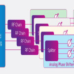
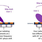
Precoding involves the individual control of the amplitudes and phases of the signals sent from the various transmit antennas. When precoding is implemented with beamforming, it can better focus energy toward the intended receiver. Various aspects of beamforming and second-generation beamforming will be addressed in subsequent articles.
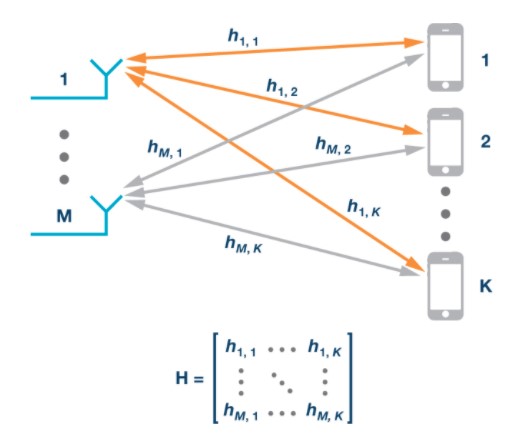
Precoding is used for various communications standards, including WiFi, 4G, and 5G. Precoding assumes that channel state information (CSI) is known at the transmitter. Precoding starts with channel sounding that involves sending a coded message (called a sounding packet or a pilot signal) to the receiver. Each of the users send back their individual CSIs to the transmitter. The users’ CSIs are used to set the precoding (spatial mapping) matrix for subsequent data transmission.
In systems using time division multiplexing (the uplink and downlink transmissions are over the same subcarrier frequency), the over-the-air transmission channels between antennas and user terminals are the same in both directions, and they are called reciprocal. Since the channels are reciprocal, CSIs only need to be determined for one direction. That enables the use of uplink-based determination of CSIs. An advantage of uplink-based characterization is that the signal processing required to determine the CSIs is performed at the base station and not in the user equipment.
Sounding is important in WiFi and 4G installations, but it is critical to maximizing system performance for 5G systems. The 5G high-frequency band is particularly challenging in terms of coverage area limitations, signal attenuation, path and penetration losses, as well as scattering. Additionally, mmWave signal bands are susceptible to blockage from buildings and other structures, particularly in higher-density urban areas. Identifying the channel performance at a given frequency requires selecting the best channel(s) for each user and optimizing communication efficiency between the transmitter and receiver.
Multi-user multiple-input multiple-output (MU-MIMO) spatial multiplexing techniques improve the spectral efficiency of 5G networks. MU-MIMO enables multiple users in the same frequency-time block while reducing interference between users. The precoding challenges become even more complex when specific users and data packets have priority and deadlines for delivery; for example, emerging applications such as autonomous vehicles must have very low latency. Each packet of data has a delivery deadline that must be met.
Traditional telephony focused on delivering a uniform, high level of quality of service (QoS) to all users. The growing variety of services that next-generation wireless networks will support will have to support a range of QoS demands. These services support both delay-tolerant and delay-sensitive applications. Scheduling in precoding is used to organize the delivery of messages based on the application’s sensitivity to delays in data delivery. Delay tolerant applications can include text messaging, some internet-of-things, and machine-to-machine applications. In addition to autonomous vehicles, delay-sensitive applications can include voice and video conferencing. And some applications, such as video conferencing, can demand a high data rate downlink, while others use only small to moderate data rates. Emerging QoS schemes are being designed to provide acceptable trade-offs between:
- Maximizing system spectral capacity through optimal utilization of inherently different QoS needs of specific users and corresponding available resource distribution.
- A measure of “fairness” to each user based on instantaneous channel conditions relative to overall average channel conditions.
- Satisfaction of latency demands of specific user applications.
MU-MIMO systems with correctly implemented precoding and scheduling can simultaneously deliver a different, application-appropriate QoS to multiple users.
As discussed, precoding exploits transmit diversity by optimizing the information stream. This is done using the channel state information supplied by the receiving device and allocating power and phases separately per frequency band. Precoding, combined with scheduling algorithms to optimize QoS for individual users and use cases, is a specific strategy chosen at the transmitter to send information to multiple receivers optimally. Following the next article on “What is beamforming,” we will dive into “What is second generation beamforming and digital beamforming?” including a look into metamaterials for beamforming, holographic beamforming, and intelligent digitally-controlled reflecting surfaces anticipated for 5G and even 6G applications.