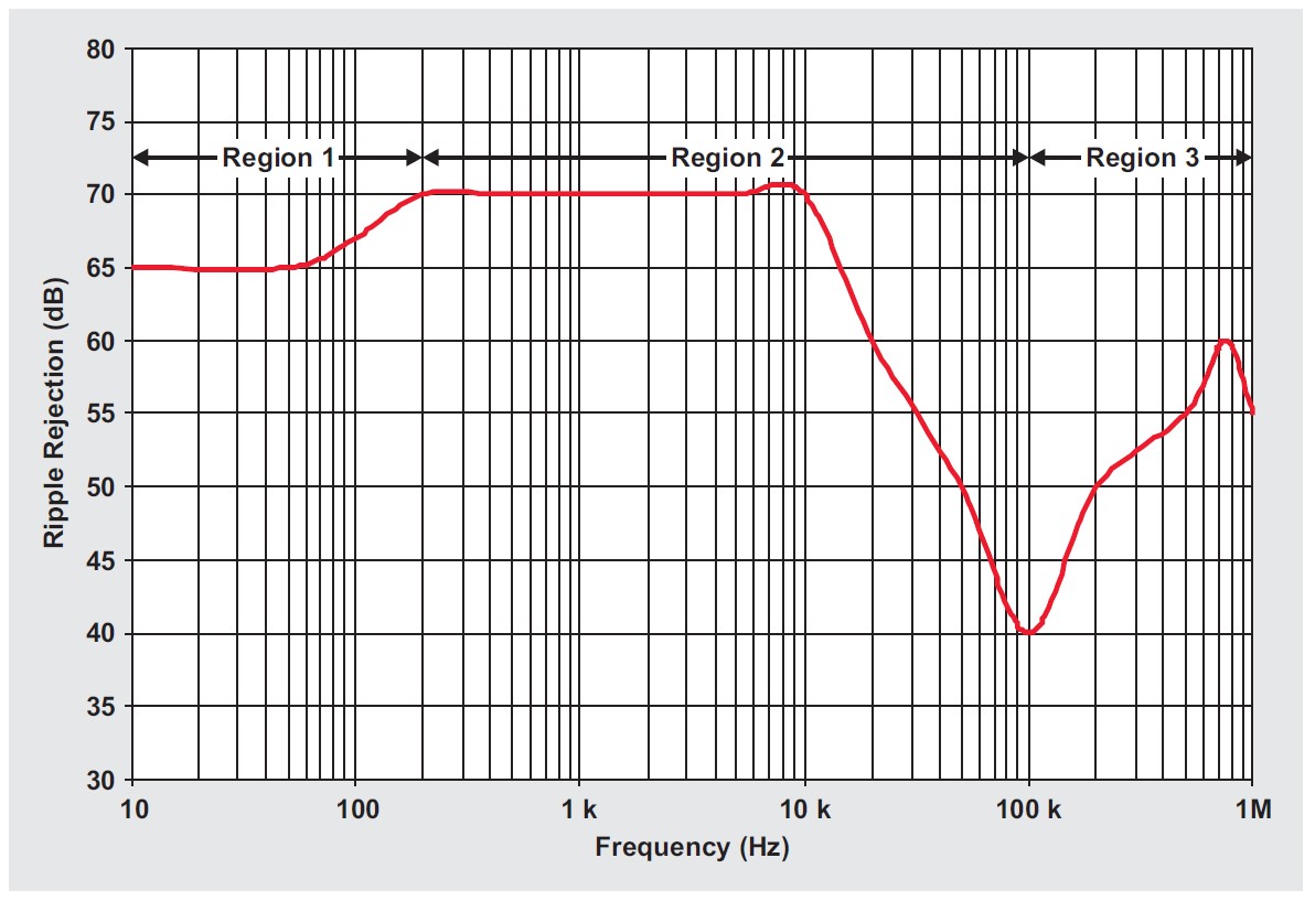
The power supply rejection ratio (PSRR) describes the ability of a circuit to suppress any power supply variations from passing to its output signal and is typically measured in dB. It’s most often used with operational amplifiers (op amps), dc/dc converters, linear regulators, and low drop out regulators (LDOs). For op amps, the PSRR describes the ability of the amplifier to maintain its output voltage as its DC power supply voltage is varied. PSRR quantifies the ability to block ripple voltage from an input source in power conversion applications.
An ideal op amp would have zero PSRR. However, the PSRR of a real op amp is frequency-dependent; the higher the signal frequency, the lower the PSRR. PSRR is commonly measured in terms of the input, but there is no industry standard. For example, when specified in terms of the input, PSRR = 10 log (ΔVsupply2Av2)/ ΔVout2), where Av = voltage gain.
In low noise and precision applications, PSRR is important for several reasons. The output of an op amp is a function of the power supply as well as the input values. Unwanted oscillation can happen if the amplifying stage is too sensitive to signals carried in through the power supply. In addition, poor PSRR results in lower efficiency. A good PSRR is important in precision automotive, industrial, and medical designs requiring minimum power consumption.
Measuring op amp PSRR
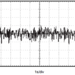
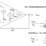
When PSRR is critical in a design, it’s recommended that designers measure its value independent of the date sheet. The manufacturer data is good but is based on assumptions that may or may not apply to the needs of a specific design, especially at higher frequencies (Figure 1). When measuring PSRR, it is typical to use balanced signals on +Vcc and –Vee to prevent common mode effects from impacting the PSRR measurement. Balanced signals may not always be present in real circuit designs, which will impact the PSRR. In addition, PSRR is related to the signal amplitude. In many application circuits, the ripple and noise on the power supply lines will be much lower than that used for developing the test data used in datasheets. In actual circuit implementations, circuit gain and PCB parasitics can also enter into PSRR.
PSRR in LDOs
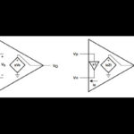
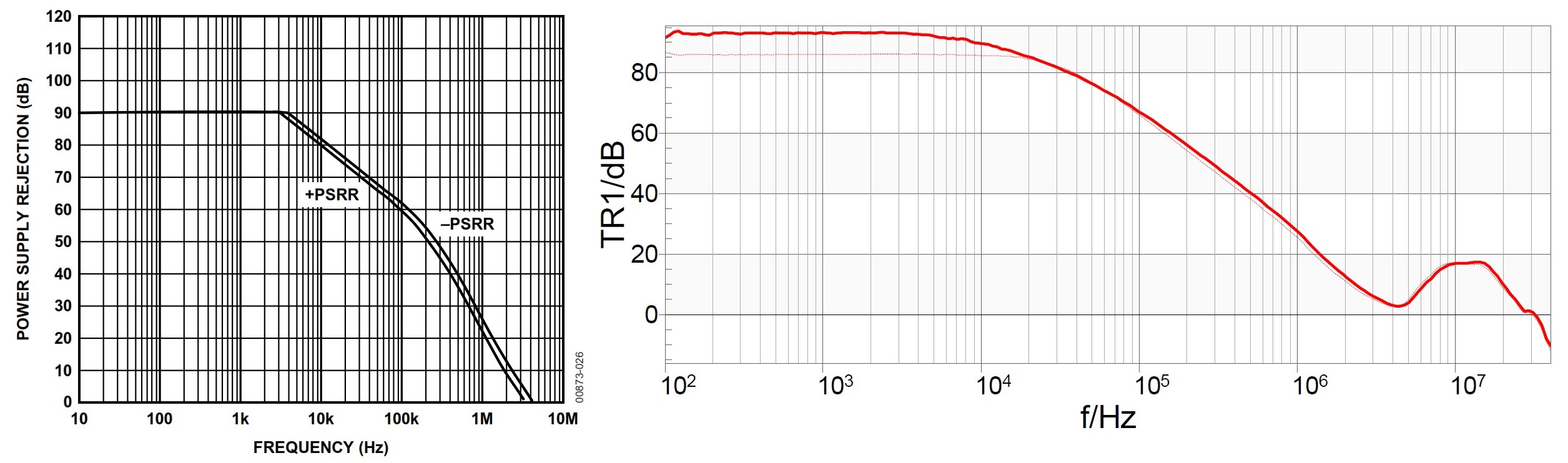
In LDOs, PSRR is sometimes called power supply voltage rejection ratio (SVRR) and measures the LDO’s ability to reject noise on the input at various frequencies (Figure 2). PSRR can be a critical parameter in audio, radio frequency (RF), and medical and other sensor applications Input ripple can have numerous sources, including 50/60 Hz interference from the mains, output ripple from an upstream dc/dc switching converter, or ripple coupled from different circuit blocks on the PCB. It’s typically measured from 10 Hz to 1 MHz or higher. For power conversion applications, PSRR = 20 log (Rippleinput/Rippleoutput).
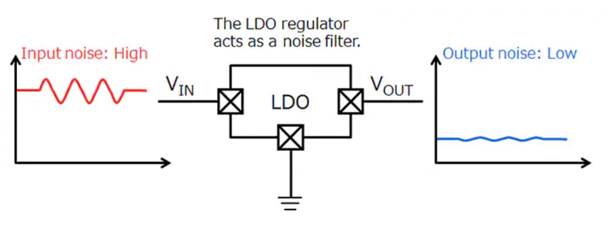
A plot of LDO PSRR includes three frequency regions (Figure 3). In the lower frequency region, up to the roll-off frequency of the bandgap filter, PSRR results from a combination of open-loop gain and bandgap factors. Above the roll-off frequency of the bandgap filter, up to the unity gain frequency, PSRR is primarily a result of the open-loop gain of the LDO. Above the unity-gain frequency, in region three, PSRR is dominated by the output capacitor and influenced to a lesser degree by parasitics between Vin and Vout. Using a larger output capacitor, with lower equivalent series resistance can improve PSRR in region three but may also impact the PSRR at lower frequencies. Instead of using a larger output capacitor, an LDO with a higher PSRR can be specified. However, LDOs with high PSRR ratings tend to need a higher supply current and can be susceptible to oscillation.
As noted, PSRR in region 2 is dominated by the gain of the feedback loop, and anything that impacts the gain also affects PSRR. For example, higher load currents tend to decrease the output impedance of the LDO, reducing the gain. In addition, a higher load current moves the output pole to a higher frequency, increasing the bandwidth of the feedback loop. The combined effect reduces PSRR at lower frequencies and increases it at higher frequencies.
Using an LDO with a DC-DC Converter
In certain situations, the combination of an LDO and a switched-mode dc-dc converter may provide an optimal power source for noise-sensitive devices. When noise is not a primary consideration, such as powering digital circuitry, a dc-dc only solution provides higher efficiency with average solution size and cost. On the other hand, using only an LDO can provide a small, simple, and reasonable cost solution but with lower efficiency.
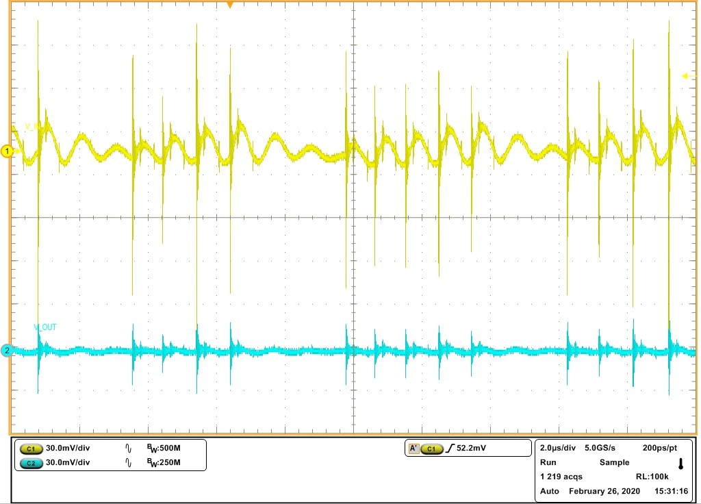
Using a high PSRR LDO with a dc-dc converter can solve with higher efficiency compared with the LDO only approach and much lower noise compared with using a dc-dc converter without the LDO (Figure 4). In fact, it produces noise just as low as the LDO-only solution. For example, in a distributed power architecture with a 12-Vdc power bus, a dc-dc converter can be used to down the bulk distribution voltage to 3.6 Vdc fed into a high PSRR LDO to provide 3.3 Vdc to power a noise-sensitive circuit element. As seen in the figure below, the ripple on the output of the LDO is in the range of tens of millivolts, much lower than the output ripple of the dc-dc converter.
Summary
PSRR Is measured in dB and quantifies the ability of a circuit to suppress any power supply variations from passing to its output signal. It’s used to describe the performance of op amps and LDOs and is important in various applications, including audio, RF, instrumentation, and sensors. In applications that are particularly sensitive to PSRR, it can be good to measure its value under actual operating conditions since it can vary from the datasheet values.
References
How can a low-noise power supply be created using an LDO regulator?, Toshiba
LDO PSRR Measurement Simplified, Texas Instruments
Measuring Op Amp PSRR, Picotest
Power supply rejection ratio, Wikipedia
Power Supply Rejection Ratio (PSRR) Real-World Perspective, onsemi
Simple Guide to Improving Ripple Rejection Ratio of LDO Regulators, Toshiba
Understanding power supply ripple rejection in linear regulators, Texas Instruments