Beamforming is an established technology for cellular communications and other applications (see the previous article on “What is beamforming?”). Beamforming was initially developed based on various analog signal chain techniques and processes. In general, beamforming combines antenna array elements to direct signals at controlled angles to maximize signal reception at specific receivers.
Analog beamforming can improve the spatial selectivity and efficiency of transmitters and receivers. Still, it suffers from limitations addressed with the next generation of beamforming based on augmented analog processing with digital technologies. The limitations of analog beamforming that can be overcome with digital beamforming or hybrid digital/analog beamforming include:
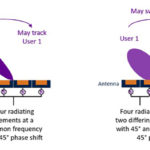
- The antenna elements are fed by a single data stream, limiting the data rate;
- Cannot provide high levels of flexibility;
- And the number of available beams is fixed in hardware.
Digital beamforming can overcome these limitations and provides greater flexibility since different signals are optimized for each antenna in the digital domain. With digital beamforming, different powers and phases can be assigned to various antennas and different segments of the frequency bands. In addition, digital beamforming supports spatial multiplexing enabling different directivity for different segments of the frequency bands (subcarriers). Frequency-domain beamforming includes the ability to support different beams for different subcarriers. Frequency-domain beamforming requires digital beamforming for implementation.
In the case of time-domain beamforming, the same beam is applied for the entire frequency carrier. Time-domain beamforming is typically implemented with analog beamforming techniques, although it could also be implemented with digital beamforming. Today, there are technology limitations that are preventing the full adoption of digital beamforming.
The baseband processor’s cost and power needs are two significant problems with full mmWave digital beamforming today. To minimize those concerns, full mmWave digital beamforming must be implemented with lower-resolution converters to keep the power consumption of the frontends within a manageable level. As a result, the gain in spatial multiplexing expected from a fully digital approach is only realized with an unacceptable cost of signal degradation.
To make matters worse, today’s communications protocols have been designed based on the assumption that analog or hybrid beamforming is employed. That limits the ability to take full advantage of the potential benefits promised by digital beamforming. In the future, the control and data channel protocols specification may be modified to enable full digital beamforming to deliver the needed low-latency communications with a high quality of service (QoS).
A promising near-term solution to the problems and limitations of employing full digital beamforming or full analog beamforming is so-called hybrid beamforming. Hybrid beamforming combines digital processing in the baseband and analog processing in the RF domain. Several hybrid beamforming solutions are under development with different system partitioning approaches between the digital and analog domains and within the domains. The common denominator is seeking an optimal combination of digital baseband processing with analog RF signal chain processing.
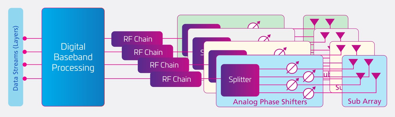
Two examples of the numerous possible hybrid beamforming architectures are the fully-connected and the sub-connected architectures. In the fully-connected structure, each RF chain is connected to all antennas. Each digital transceiver’s transmitted signal goes through a dedicated RF path (with mixer, power amplifier, phase shifter, and so on). It is summed before being connected to the antenna. This approach results in high performance but suffers from high complexity and energy consumption. Full beamforming is realized for every transceiver using this approach, envisioned for use in base stations and similar fixed installations.
A different approach called a sub-connected beamforming architecture is more suited for handsets and other applications such as vehicles. In sub-connected beamforming, each RF signal chain is connected to only a subset of the available antennas. That makes the sub-connected architecture simpler and more power-efficient, but it is less spectrally efficient and unsuited for large installations where spectral efficiency is important.
New approaches to beamforming and mmWave transmissions are also being developed to complement existing analog and hybrid approaches. For example, holographic beamforming also shapes the antenna’s radio pattern under software control. It can be considered to be a software-defined antenna. And a recently-developed electronically-scanned antenna technology, called metamaterial surface antenna technology, is based on a diffractive metamaterials concept and achieves electronic scanning using high-birefringence liquid crystals. For more information on these developments, see: “Metamaterials, mmWave antennas, 3D radar, and holographic beamforming.”
In addition to metamaterial antennas and holographic beamforming, there is an interest in developing metamaterials to fabricate intelligent, digitally-controlled reflecting surfaces for use with 5G and future 6G networks. The IEEE Signal Processing Society recently announced the eighth edition of the Signal Processing Cup: the challenge is to control a wireless propagation environment using an intelligent reflecting surface. This challenge aims to develop “an intelligent reflecting surface is a two-dimensional array of metamaterial whose interaction with electromagnetic waves can be controlled, e.g., by tuning the impedance variations over the surface. These surfaces might be used in 6G to direct wireless signals from a transmitter toward a receiver. The challenge’s goal is to characterize the behavior of an intelligent reflecting surface based on data from over-the-air signaling and develop a control algorithm to configure the surface to aid wireless communications.”
Digital beamforming and related technologies for 5G communications are evolving as rapidly as they are emerging. These and related technologies, such as intelligently-controlled reflecting surfaces, are expected to become important elements in designing future 5G installations.