Many use the term “attenuation” without completely understanding it. The term is used in several areas, including medical, audio, and even attenuation terminology associated with brewing beer. Generally speaking, attenuation means “lessening” the thing that’s being attenuated. For example, sunglasses attenuate the sunlight reaching your eyes. Attenuating an electrical signal can mean that the act of attenuation improves or enhances the wanted signal by lessening the unwanted portion. However, signal attenuation does not mean boosting or increasing the strength of a signal.
In transmitting electronic signals, attenuation is the loss of signal strength as measured in decibels (dB). For instance, signals transmitted from a cell tower to your phone can become distorted from increased attenuation as you walk around the corner of a building. Wireless signal strength can be attenuated (lessened) due to noise, physical barriers, and long distances. As signal attenuation increases, full signal transmission decreases. Attenuation rates in cabling are affected by external sources of noise at frequencies that penetrate the signal carried by the cable. Fiber optic cables are excellent at transmitting with low attenuation rates because they transmit signals in the form of light waves before changing them back to electronic signals on the receiving end. High-frequency wavelengths of light used for transmitting signals inside fiber optic cable is resistant to noise until it is transformed (modulated/demodulated) into electronic signals.
Attenuation is the opposite of amplification. If you turn the volume down on your radio, it’s reducing the amplification of the signal, not attenuating it. The same signal may be attenuated by a filter that removes all unwanted signals above a certain frequency. A low pass filter lets all low-frequency signals pass through the filter and attenuates signals above the filter’s stopband attenuation level. Attenuation is related to “insertion loss” and is often found in datasheets. However, insertion loss is specifically the signal energy that’s lost when a device is inserted into a circuit.
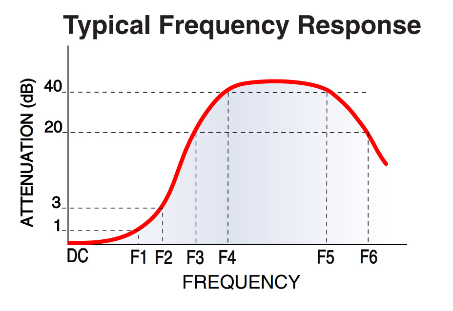
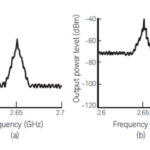
Figure 1 is a graph from a datasheet for a low pass filter. The attenuation of a signal through the low pass filter increases as the signal frequency increases. The signal above frequency F1 is increasingly absorbed. The signal attenuation below frequency F1 is not linear, but close enough at a level of less than 1 dB of attenuation. The rate of attenuation is higher above F1 and stops increasing after around the frequency at F4.
Attenuation for electrical signals has a formula:
Attenuation (dB)= 10 X log(PI/PO)
Where PI is input power and PO is the output power. PI is the power applied at one end of the cable, while PO is the wattage at the end of the cable.
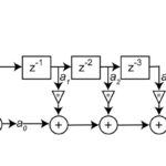
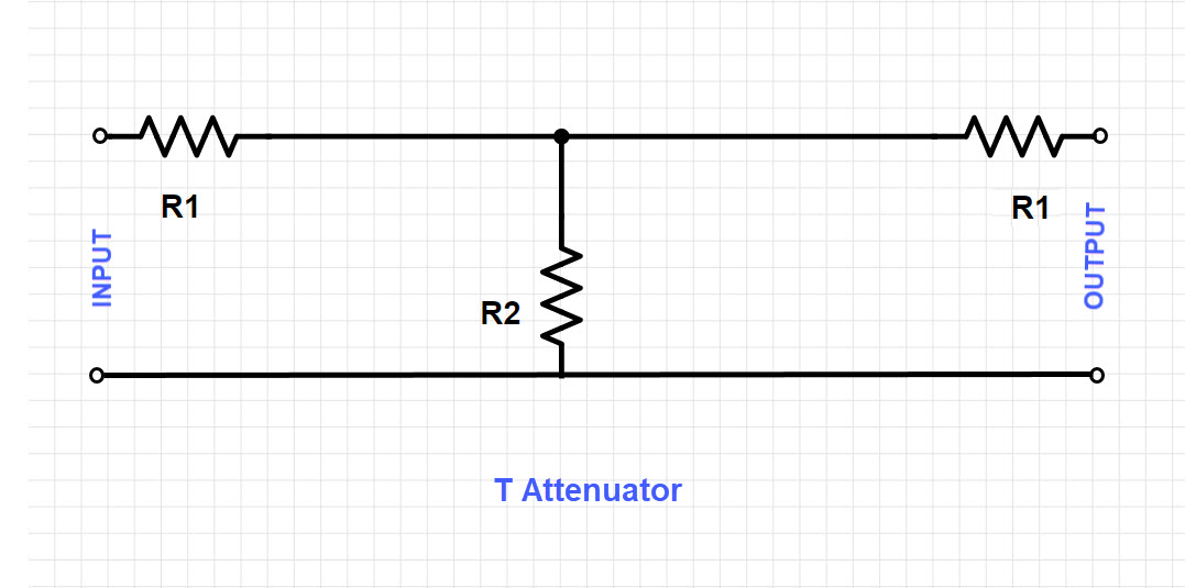
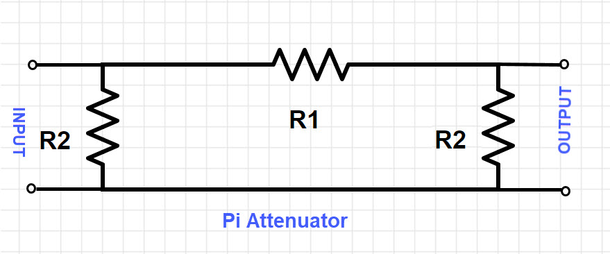
An attenuator is a passive or active circuit that can attenuate a signal. The passive type is often just a resistor divider but could also be followed by a buffer (a type of op amp). The active type of attenuator can be an inverting op amp attenuator or fully differential op amps.[i] The attenuator should match source and load impedances in addition to the desired attenuation. There are a few attenuator calculators online for T attenuators and Pi attenuators.
Besides T- and Pi attenuators, other types of fixed passive attenuators are laid out in L, H, and O configurations, too. Other attenuator types include continuously variable, programmable, DC passing, DC blocking, waveguide, and optical attenuators.
Attenuator design can become complex if the impedance is not already the same between the input and output (load) sides where the attenuator will be placed since balancing impedance would be necessary. Performance can vary so design trade-offs may need to be juggled in an attenuator’s frequency range, switching speed, linearity, insertion loss, and ruggedness.
We’ve discussed the basics of attenuation above. However, attenuation is almost a science to itself in electronics alone as attenuators have expanded from a simple connecting circuit made of passives to integrated chips that provide stepwise-tunable digital attenuation. Attenuation is also a similarly identifying term used in medicine, physics, acoustics, fiber optics, nuclear power, materials science, biology, seismology, radiology, and many other disciplines.
[i] https://www.ti.com/lit/an/slyt336/slyt336.pdf
[ii] https://www.connectortips.com/faq-what-are-attenuators/