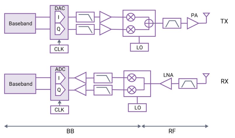
The 5G RF/mmWave signal chain is expected to be the same as, and different from, the RF signal chain for today’s LTE Advanced devices. 5G consists of two separate frequency bands, FR1 is mostly repurposed LTE bands, and FR2 bands are in the mmWave region. As a result, 5G in the FR1 frequencies can use a zero-IF (or direct) conversion radio architecture like the one currently used in LTE cell phones, Bluetooth, and similar devices. The FR1 section of 5G devices will be able to use similar RF modulation/demodulation architectures, and similar analog front ends. They won’t be identical because 5G will have more bandwidth than LTE. But the increased bandwidth can be accommodated with quite similar technologies.

A zero-IF receiver, also called a direct-conversion receiver, homodyne or synchrodyne, is a radio receiver design that demodulates the incoming radio signal using synchronous detection driven by a local oscillator whose frequency is identical to or very close to the carrier frequency of the intended signal. This is in contrast to the standard superheterodyne receiver, which is accomplished only after initial conversion to an intermediate frequency (IF). Compared with superheterodyne technology, zero-IF radios are simpler in design, occupy less PCB space, are more energy efficient, and lower cost.
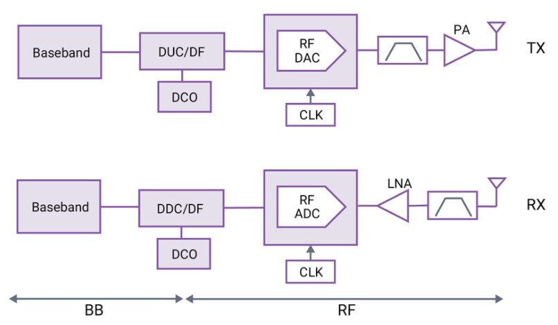
In a direct RF sampling architecture, a data converter digitizes the signal directly at RF and hands it off to a signal processor to obtain the available information. This fundamental design change takes what has traditionally been handled by analog processing (mixers, local oscillators, filters, and amplifiers) into the digital domain.
A new class of direct RF sampling analog-digital-converters (ADCs) capable of multiple gigasamples per second (GSPS) has been developed, allowing much higher conversion rates with lower power consumption. In addition, direct RF sampling enables more digital integration, which is used for a low-power, multi-gigabit serial interface and on-chip digital-down conversion (DDC). Combined, they make for a very size- and power-efficient digital interconnect between the data converter and digital processor. Because analog frequency conversion is not required, the overall hardware design of a direct RF sampling receiver is much simpler, enabling a smaller form factor and lower design cost.
Increasing RF signal chain complexity
RF signal chain complexity in mobile infrastructure and devices has increased with each generation of wireless technology. 5G adds yet another level of complexity, intensifying the challenges for mobile device design engineers. Radio frequency front-ends (RFFEs) in 5G devices must support many more RF paths, with higher power output and much greater bandwidth, all while occupying less space. Minimizing link losses and efficiently removing heat is vital. Advances in filter technology are critical to achieving these goals.
RF power output in mobile devices has increased due to requirements such as Power Class 2, a specification introduced by 3GPP to improve 2.5 GHz TDD-LTE coverage worldwide. Power Class 2 raises power output at the handset antenna by 3 dB to increase the uplink (UL) range. This specification is also used to support the new FR2 5G bands.
In addition, handset manufacturers require RFFE components that handle higher power to maintain adequate design margins as system losses increase due to growing RF complexity. In today’s mobile and infrastructure devices, filters must handle power levels as high as 33 dBm or more. Filters can maintain performance and avoid lifetime degradation by effectively dissipating the heat caused by these higher input power levels.
And thermal management, in general is increasing in complexity and is more critical. 5G devices will combine envelope tracking (ET) and average power tracking (APT), depending on the subsystem’s needs. APT is simpler to implement and provides a coarser power consumption control than ET. APT tracks the average power consumption of an RF power amplifier (PA). Adjustment to the PA supply voltage occurs whenever average output power changes. ET, in contrast, continuously adjusts the voltage applied to an RF PA to ensure that the PA is operating at peak efficiency given the power needed during each instant of a transmission.
Both LTE and 5G transmissions can have a very high peak-to-average power ratio (PAR). ET can improve system efficiency at high power levels with high-PAR signals. For example, system efficiency improvement of more than 23% (from 30% for APT to 39% for ET) is achieved at +28 dBm PA average output power.

Carrier aggregation in 5G
Carrier aggregation (CA) is a technology that combines two or more carriers into one data channel to enhance the data capacity of a network. Using existing spectrum, CA helps mobile network operators provide increased uplink and downlink data rates. CA is used to increase throughput in 4G, which will be just as important for 5G.
CA in 5G new radio (NR) will provide multi-connectivity with asymmetric upload and download, providing even more bandwidth to a single user; up to 700 MHz is available in mmWave frequencies. In the sub-7 GHz band, up to 400 MHz of instantaneous bandwidth can be achieved using four 100 MHz channels. Since 5G employs FR1 (existing LTE bands) and FR2 (mmWave bands), CA will require more complex implementations. The use of data converters that deliver multiple GSPS not only supports RF channel bandwidths from 100 to 400 MHz, it supports the need to process multiple channels, or the complete 5G band, to reduce the number of TX/RX chains and allow channel selection and CA to be implemented in the digital domain.
Maximum performance for 5G NR designs will require using both the FR1 and FR2 carriers simultaneously. Called LTE-NR tight-interworking, also known in the 3GPP specifications as Evolved Universal Terrestrial Radio Access (EUTRA) + NR – dual connectivity (DC), usually abbreviated as EN-DC. With this new network architecture, existing LTE radio and core networks are used as a master entity for mobility management and coverage while adding a new secondary 5G carrier.
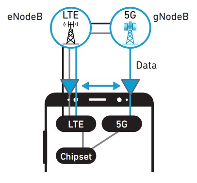
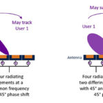
Two high-power signals are transmitted from one phone with EN-DC: the LTE anchor signal and the NR data signal. This configuration requires two complete uplink signal paths in the small area of a mobile phone, which presents major design challenges for engineers. High isolation between these two signal paths is critical in limiting intermodulation products and meeting out-of-band emissions specifications. However, additional considerations related to signal conditioning, RF module design, and the various antennas are also important factors.
That brings the discussion to the antennas used in 5G designs. The first article looked at “Basics of mmWave and its applications” in general. This second part has looked into a single application of mmWaves and looked at “What is the 5G RF/mmWave signal chain?” The third and final FAQ in this series will consider some of the details of “mmWave antennas and antenna management for 5G.”
References:
A new generation of 5G filter technology, Qorvo
Direct RF conversion: From vision to reality, Texas Instrument
Evolution of Carrier Aggregation (CA) for 5G, Qorvo
Very High-Speed Data Converters for 5G Analog Front-End, Synopsys
Wideband Receiver for 5G, Instrumentation, and ADEF, Analog Devices