Many antennas are mechanically simple and electrically complex at the same time. Mechanically an antenna usually has only one or two components, a dielectric layer (which can be the entire antenna) and a conductive layer. This FAQ begins with a brief review of dielectric materials and their importance to antenna performance. It then explores developments related to advanced antennas for 5G handsets, antennas for flexible electronics, and the possibility of using carbon nanotube-based antennas in wearables.
The selection of the dielectric material can impact the mechanical and thermal properties of an antenna as well as its electrical performance. There’s a wide range to choose from: polystyrene foam or honeycomb structures have a lower dielectric constant (between 1 and 2), fiberglass reinforced polytetrafluoroethylene (PTFE) has a relative dielectric constant (between 2 and 4), and ceramic, quartz and alumina have even higher values. A material with a high dielectric constant and a low dielectric loss can be used by itself to fabricate an antenna.
Use of a material with a high dielectric constant is important when designing miniature antennas since there is a frequency shortening effect. Ceramics are attractive due to their low dielectric loss and high dielectric constant. But they are brittle and difficult to work with. Instead of pure ceramics, ceramics are used in polymeric matrices and composites when designing antennas. Another challenge when using ceramics is that the dielectric constant cannot be easily (if at all) adjusted for specific application needs. When used in matrices or composites, the amount of the ceramic can be adjusted, allowing the dielectric constant of the resulting material to be optimized. A wide range of ceramic concentrations and particle sizes are used in these dielectrics, with particles ranging from 0.2 to 10 μm and volume amounts of ceramic in the mixture between 10% and 70%. More recently, anodized aluminum oxide (AAO) has been developed for use in miniature antennas in 5G handsets.
AAO and 5G
Designers of 5G handsets are always challenged to find more space-efficient antennas. 5G handsets are high-density assemblies, limiting the degree of freedom related to the space and locations available for antennas. That makes antenna miniaturization especially important.
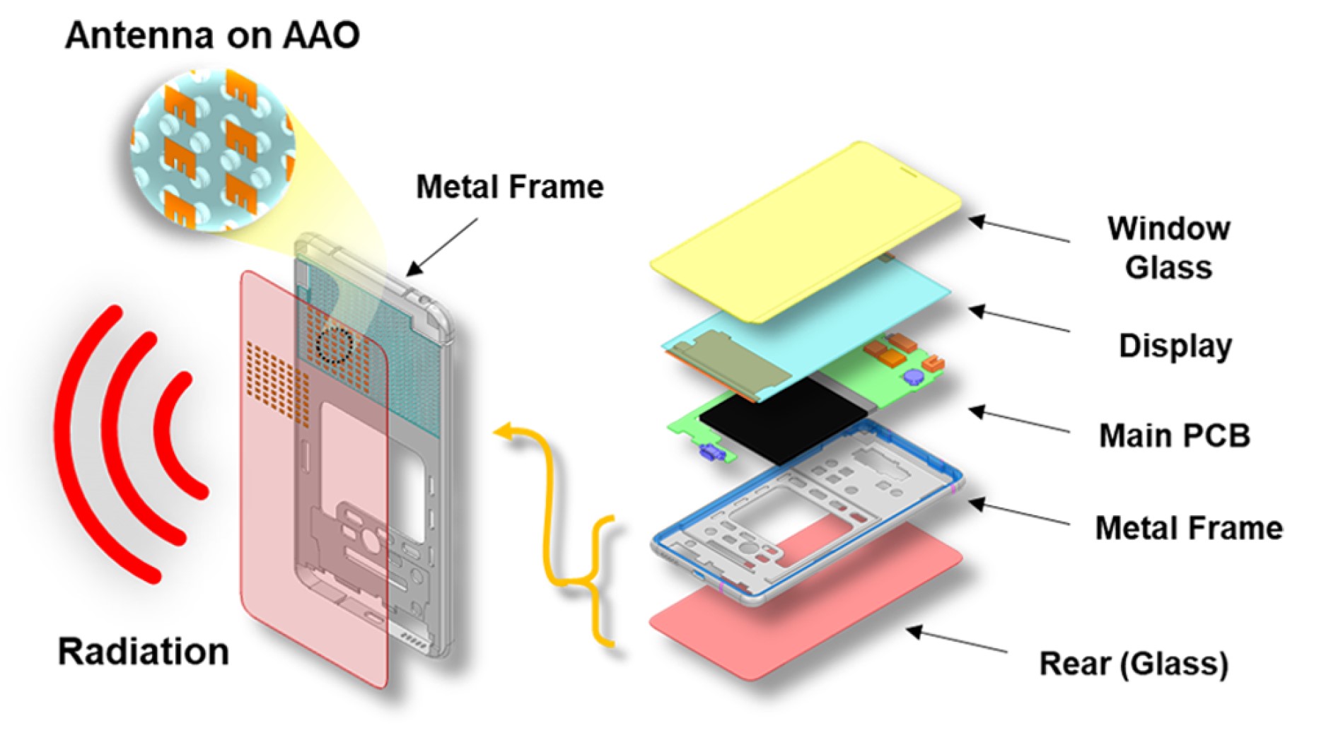
A recent design targeting 5G handsets places a dielectric layer on an aluminum surface using AAO. The antenna is then placed on the dielectric. The envisioned AAO-based structure reduces the size of the antenna (1.87 mm (0.18 λ0) × 2.34 mm (0.22 λ0)). The AAO layer has a higher dielectric constant (εr) of 6.7 compared with other dielectric materials such as polycarbonate (εr = 3.5) or FR4 substrate (εr = 4.4) that are currently used to fabricate antennas. And this approach increases design freedom since it enables precise control of the dielectric layer dimensions and produces a dielectric layer on the metal substrate. The AAO antenna has a gain of 5.02 dBi and resonates at 29 GHz.
The high dielectric constant is essential for this antenna’s small size and good performance. The AAO dielectric layer can be applied to the aluminum metal frames used in current handset designs, and the dielectric and ground layers can be manufactured as a single unit, further increasing the design freedom for the antenna. The AAO-based antenna can be integrated into the metallic middle frame of the mobile phone, facilitating the construction of a massive antenna array in a limited space (Figure 1).
In addition to mobile phone handsets, 5G is used in many wearable devices such as the internet of things (IoT), personalized medicine platform, fitness monitors, wireless sensor networks, gaming, and various communication devices. These wearables need non-rigid, flexible antennas. The choice of materials for these antennas is complex.
Flexible antennas for flexible electronics
Factors affecting the choice of materials for flexible antennas include the environment where the device will be used, the need for seamless integration with rigid and/or non-rigid devices, suitability for mass production, cost, and so on. High conductivity is necessary to ensure adequate performance in terms of gain, efficiency, and bandwidth, and materials such as silver or copper nanoparticle (NP) inks, copper tapes, conductive polymers, polydimethylsiloxane (PDMS)-embedded conductive fabrics, and graphene-based materials are used.
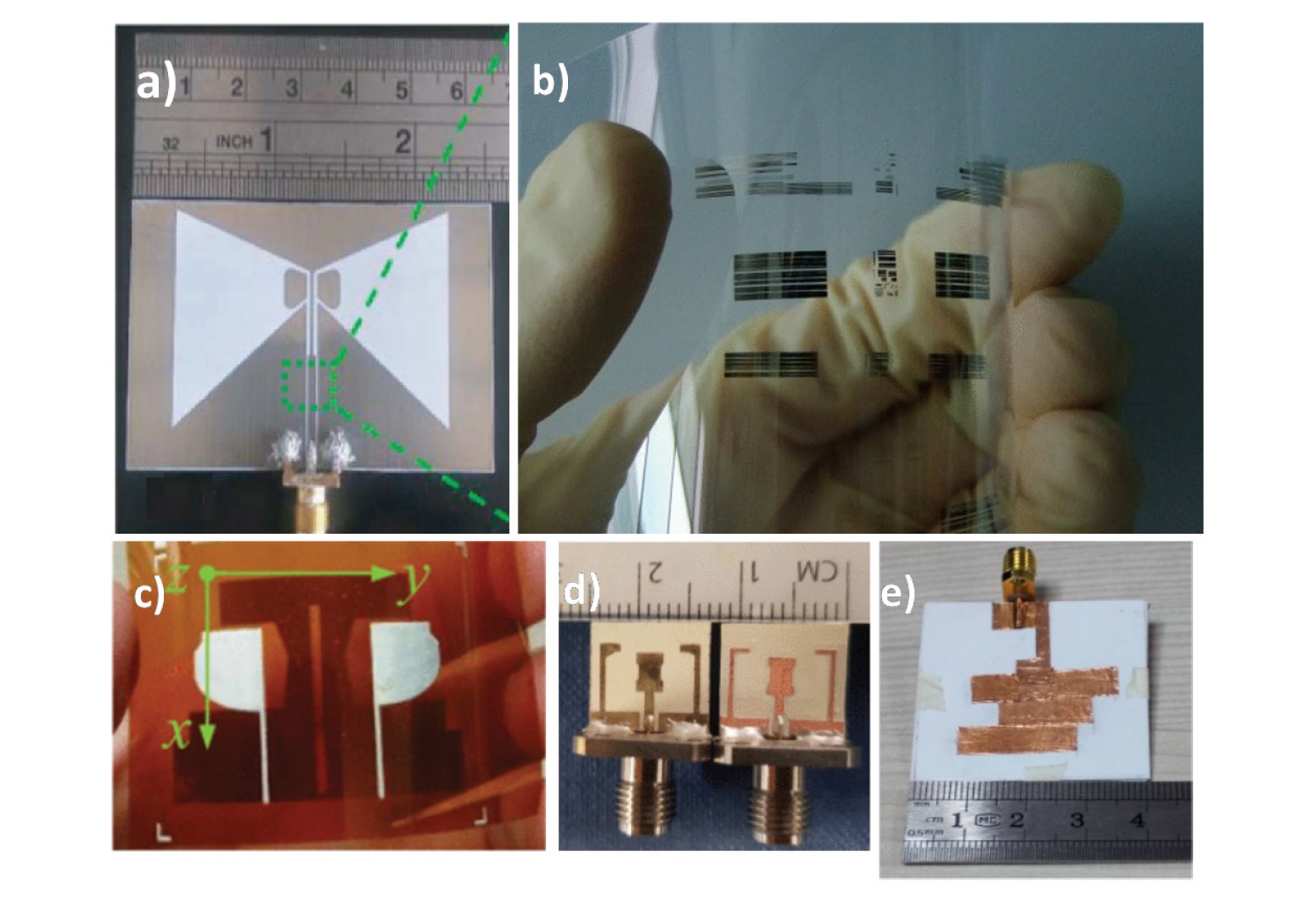
NP inks can be used to produce flexible antennas. While both copper and silver NP inks have adequate conductivity for antenna fabrication, silver is less subject to corrosion and is preferred in many applications. In addition to NP inks, nonwoven conductive fabrics (NWCFs) and electro-textile materials, such as nickel/silver-plated Flectron (copper-coated nylon fabric), are used in flexible antennas. Copper tapes, copper cladding, and adhesive copper have been used but are not favored due to their lack of environmental ruggedness and susceptibility to corrosion. Dielectrics and substrates are other important areas of material development. Numerous substrate choices exist, including kapton polyimide, PANI, PEN, PET, liquid crystal polymer, electro-textile, and e-paper (Figure 2).
Flexible antennas have been developed for low-frequency applications and use above 12 GHz. Bending, stretching, and proximity to the human body can significantly impact the performance of flexible antennas. Designing antennas with higher bandwidths or improved symmetry can help ensure performance across various challenging conditions.
CNT antennas for wearables
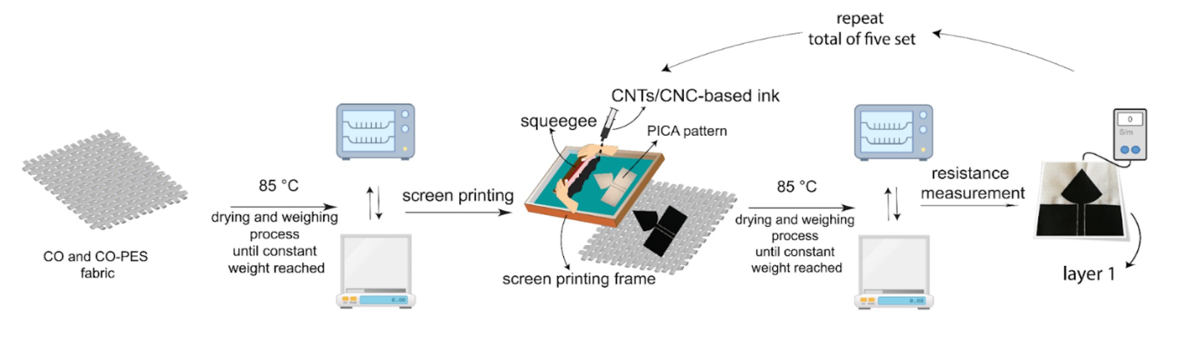
The use of metallic conductive inks to fabricate antennas on wearables has limited utility. Those inks can become oxidized over time and lose performance. Plus, they can be heavy and relatively inflexible. One avenue being pursued in the development of flexible antennas is the use of hybridized carbon structures such as graphene and carbon nanotubes (CNTs). These materials combine strong mechanical properties, high corrosion resistance, low density, high electrical conductivity, and high thermal stability. CNTs are particularly attractive because of their high current mobility and low cost of production. The conductive CNTs can be suspended in cellulose nanocrystals (CNC) ink and printed onto woven fabrics in a layer-by-layer fashion until multiple layers have been formed (Figure 3).
A polyurethane composite mixed with multiwall carbon nanotubes (PU/MWCNT) was used in a separate development effort. As with the CNT-based antenna described above, these antennas were fabricated by building up a series of layers. A dual-band unipole and a dual-band F-antenna were designed for operation in the 2.45 and 5.18 GHz bands. The carrier substrate for the antennal was 2 mm thick polypropylene (PP), which acts as a ground plane to improve antenna performance.
The antenna feeds were a combination of a short 50 Ω section on the PP substrate and an 18 mm long 50 Ω section on an FR4 substrate (Figure 4). The ground layer of the PP and the microstrip line consisted of 35 μm thick self-adhesive copper foil. Electrical connections between the microstrip lines on the PP substrate and the FR4 and between the PU/MWCNT composite and the microstrip were made using a conductive silver compound. The unipole antenna included a simple LC matching circuit to improve S11. The F-antenna does not use the matching since the 50 Ω impedance can be realized by optimizing the L, L1, and L2 dimensions.
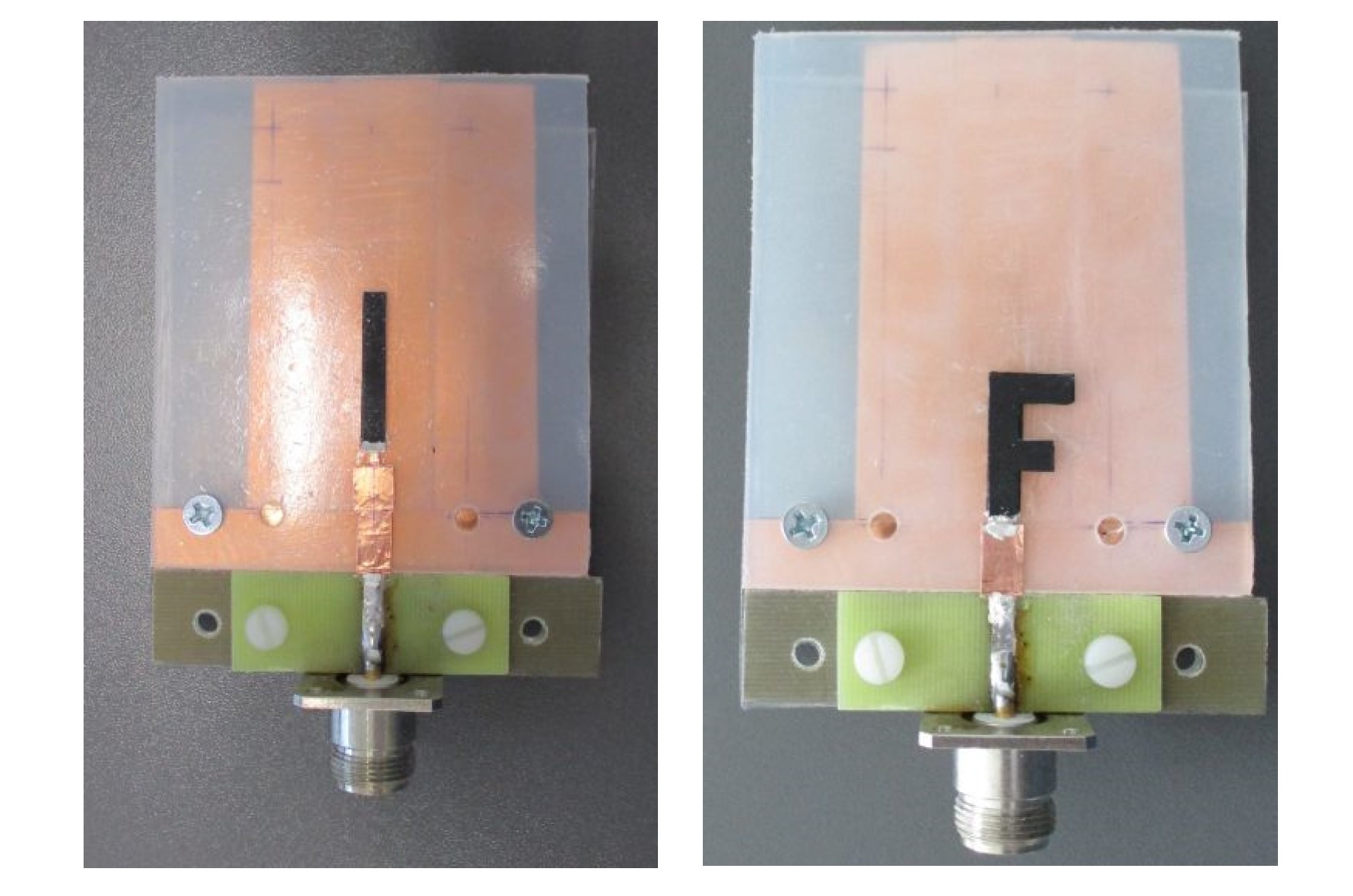
The gain of the unipole antenna was -10.0 and 5.5 dBi for 2.45 and 5.18 GHz frequency bands, respectively. The gain of the F-antenna was lower since it used a thinner layer of the PU/MCNWT composite compared with the thickness of the composite for the unipole.
Summary
Antenna miniaturization is an active area of development. Numerous efforts have focused on improvement in the performance of dielectric materials, such as AAO, for use in antenna matrices in 5G handsets. Various substrate (dielectric) and conductor combinations have been developed for the flexible antennas needed in flexible electronics. Recent efforts have been focused on the use of CNT-based antennas in wearables. Advances in antenna miniaturization rely on the convergence of materials science and electronics developments.
References
Enhanced Planar Antenna Efficiency Through Magnetic Thin-Films, IEEE
Flexible Antennas, MDPI micromachines
Future Antenna Miniaturization Mechanism: Magnetoelectric Antennas, IEEE International Microwave Symposium
Miniature Millimeter-Wave 5G Antenna Fabricated Using Anodized Aluminum Oxide for Mobile Devices, ACS Omega
Polyurethane-Carbon Nanotubes Composite Dual Band Antenna for Wearable Applications, MDPI polymers
Screen Printing Carbon Nanotubes Textiles Antennas for Smart Wearables, MDPI sensors