A logarithmic resistor ladder consists of a resistor string and switches designed to attenuate a signal. The state of the switches can be considered to represent a digital code proportional to the logarithm of the attenuation ratio. Logarithmic attenuation is useful when a large dynamic range is needed. Audio volume control and fading/balancing audio signals are the most common uses of logarithmic resistor ladders. Still, they are also used in general-purpose signal attenuation and adjustable gain circuits. This FAQ begins with a general discussion of logarithmic resistor ladders in audio systems, presents discrete implementations of logarithmic resistor ladders, and closes by considering the benefits of using logarithmic resistor ladder ICs.
Logarithmic ladders are often used in place of a potentiometer (pot), the most common volume control device. With a potentiometer, there are no ‘steps,’ and the change in resistance is smooth and continuous. But pots aren’t perfect.
Problems with pots
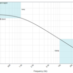
In a volume control pot, the midpoint of the rotation usually results in about 20 dB of attenuation. Attenuation increases rapidly in the first half of the range, with finer control over higher volume settings in the upper half of the rotation range. The use of pots has several drawbacks. Particularly in small portable devices, there is not adequate space to include a pot, and some form of real or virtual buttons are often used together with a processor to control the volume.
Even with adequate room for a potentiometer, ganged pots used in stereo systems suffer from mechanical tracking issues. The left-right balance is not maintained and can change over time as the pot experiences mechanical wear. As a result, several alternatives have been developed to replace pots for audio volume controls.
Logarithmic resistor ladders and stepped attenuators
Logarithmic resistor ladders and various stepped attenuators have been developed to replace pots in audio volume control applications. There are a fixed number of discrete attenuation steps (Figure 1). The number of steps is usually limited to a few dozen. In most cases, the stages are arranged in an order that results in smooth changes in attenuation, but since the stages operate independently, the stage order can be arbitrary.
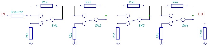 Figure 1: Basic 4-stage logarithmic resistor ladder, most practical designs have a few dozen stages. (Image: Wikipedia)
One common implementation of a logarithmic resistor ladder is the stepped attenuator. A stepped attenuator is a large rotary switch with several precision resistors arranged to form a logarithmic ladder (Figure 2). Like vinal recordings, stepped attenuators are preferred by some audiophiles that prefer the sound from stepped attenuators over the sound from pots.
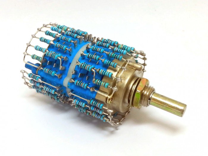 Figure 2: Mechanical stepped attenuator using a rotary switch. (Image: Tortuga Audio)
One major limitation of stepped attenuators is that the mechanical complexity and cost of the devices increases dramatically when more steps are added. That limits them to about 30 steps, too few to provide smooth volume changes over an extended dynamic range. In addition, the mechanical switching mechanism produces clicking and popping artifacts into the audio as the volume is changed. Even when the clicks and pops are mitigated as much as possible, the mechanical nature of the device is prone to wearing out and deteriorating operation.
Electronic potentiometers
An electronic pot is a circuit that combines the benefits of a pot and a stepped attenuator and provides additional functionality. An electronic pot is a resistance-based volume control similar to a pot or stepped attenuator, but with the addition of digital control. The digital circuitry supports multiple functions such as input switching, muting, channel balance adjustments, power on/off control, and volume control. It can also drive a flat-panel display for a user interface.
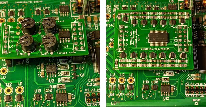
Depending on the design, an electronic pot can be implemented using discrete precision resistors with an electronic switching IC or a series of light dependent resistors (LDRs) (Figure 3). A single LDR can replace multiple-precision resistors. The resistance of an LDR changes by several orders of magnitude as the light level changes. In some cases, the resistance can be several MΩ in darkness and only 100 Ω in high light levels. When choosing between an LDR and precision resistors, there are tradeoffs related to linearity, stability, and temperature dependence.
Digital logarithmic resistor ladder ICs
Digital logarithmic resistor ladder ICs consist of integrated resistors, FET switches, and digital controls. They are available with both linear resistance ladders and logarithmic ladders. If not properly designed, process variations between different ICs can result in resistance variations up to ±30 percent. In some applications, resistance variations between ICs are not a critical consideration. However, in the case of stereo audio, large variations in resistance values are undesirable and can result in poor performance. In addition, not all digital resistor ladder ICs include a make-before-break function to ensure the glitch-free operation needed in audio systems.
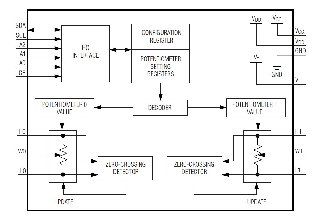
Logarithmic resistor ladder ICs are available for audio applications with 32 steps and 1 dB between each step. These devices can be controlled using a 2-wire serial interface and include zero-crossing detection to minimize any audio noise resulting from step transitions (Figure 4). These IC have nominal resistor temperature coefficients of 35ppm/°C end-to-end and 5ppm/°C ratiometric to ensure consistent performance.

Logarithmic resistor ladder ICs are available with dual digital potentiometers for stereo audio. The use of separate power supplies for the potentiometer function and the communication circuitry ensures reliable operation. In addition to zero-crossing detection, these ICs feature 0.5 dB channel-to-channel matching to prevent volume differences between channels (Figure 5).
Summary
Logarithmic resistor ladders commonly replace potentiometers in audio applications such as volume control and fading/balancing. These circuits can be designed using discrete precision resistors with mechanical switching or digital controls. In some embodiments, a single light dependent resistor is used to replace a string of discrete resistors. For applications where size is especially important, designers can turn to single-channel or dual-channel digital logarithmic resistor ladder ICs.
References
Audio Gain Control Using Digital Potentiometers, Maxim/Analog Devices
Electronic Stepped Attenuator Overview, Tortuga Audio
Logarithmic resistor ladder, Wikipedia