Equalizers are used to alter the performance of signal chains. In some cases, that means linearizing signal chain performance. In other cases, equalizers are used to introduce nonlinearities. As a result, equalizer designs vary widely from simple passive circuits to complex multi-stage designs and active circuits.
This FAQ reviews equalizer basics, looks at equalizers for radio frequency (RF) and audio applications, and closes with a brief look at how equalizers are applied in visible light communications and renewable energy systems.
The term ‘equalizer’ is generally used for networks designed to compensate for varying amplitude characteristics of a system; in some cases, this type of equalizer may provide some level of phase correction as a secondary outcome. The terms ‘phase equalizer’ or ‘phase corrector’ are used for networks where phase correction is the primary goal.
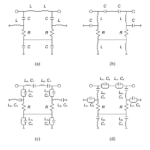
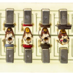
Lattice and bridged-T equalizers are examples of all-pass filters. They are often used to correct amplitude and/or phase errors in a signal chain, to deliver a system with a flat amplitude response and constant delay over a defined frequency range (Figure 1). A lattice phase equalizer has constant attenuation at all frequencies, but the relative phase between input and output varies with frequency. The lattice filter topology is a constant-resistance network and is easily combined with other constant resistance filters such as bridge-T equalizers.
A bridged-T can be used to insert a constant delay at all frequencies in a signal chain. It’s often the choice when two or more signals need to be matched based on a timing criterion. When balancing a single-ended circuit, the bridged-T is often used, and when equalizing a balanced transmission line, a lattice configuration is usually preferred.
RF gain equalizers
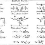
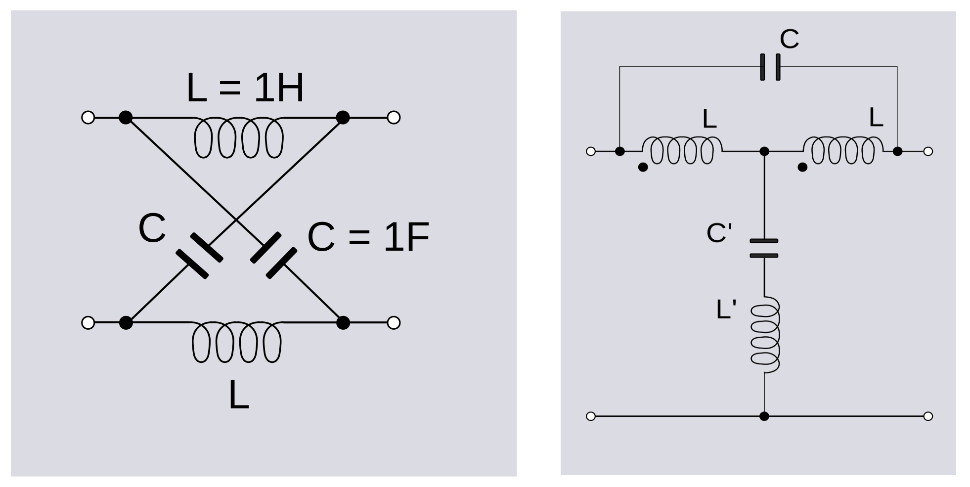
The gain of most RF amplifiers decreases at higher frequencies. In addition, other signal chain components such as cables and passive components can add insertion losses that increase at higher frequencies. An RF gain equalizer can compensate for RF amp performance only or the combination of the RF amp and other elements in the signal chain (Figure 2).
Due to the widely varying uses of RF gain equalizers, there’s an equally wide variety of design considerations. Three of the most common include:
Operating frequency range – For example, L-Band or Microwave gain equalizers. L-Band designs are used between 950 MHz and 2.15 GHz. Microwave Gain Equalizers are typically used are frequencies from 2GHz to 20GHz.
Gain slope – RF equalizers can have positive, negative, positive parabolic, or negative parabolic-shaped gain slop functions. Positive gain slopes have increasing insertion loss with frequency. Negative gain slopes have decreasing insertion losses with frequency. Parabolic RF equalizers have nonlinear, parabolically-shaped gain slopes.
Active vs. passive – Active gain equalizers need an external power supply and use an amplifier to produce a positive gain. Passive gain equalizers do not use an amplifier and produce an insertion loss.
Audio equalizers
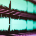
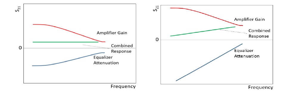
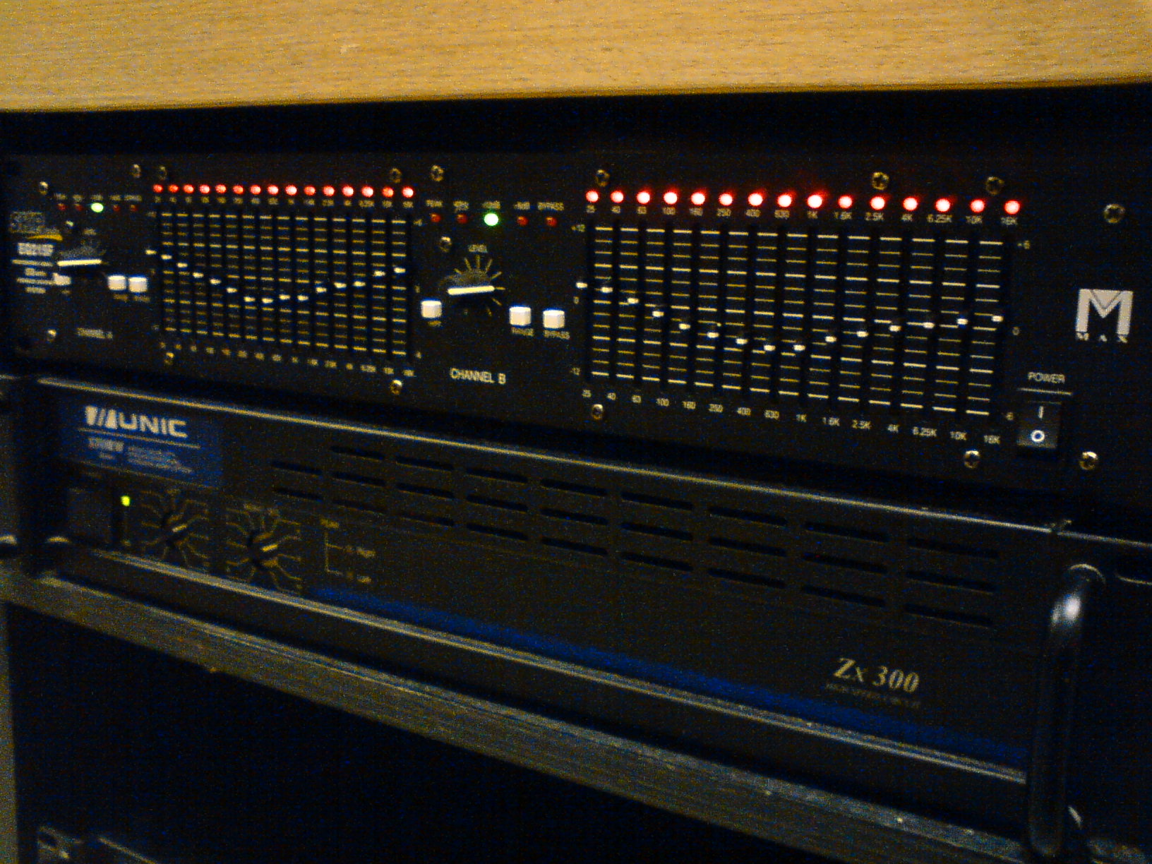
While RF equalizers compensate for various sources of non-linearity in the RF signal chain, audio equalizers are often used to introduce nonlinearities and ‘shape’ the sound. So-called graphic equalizers (EQs) are a collection of fixed-frequency peak and notch filters designed to simultaneously cut or boost several predefined frequencies (Figure 3). For example, 31-band, ‘one-third octave,’ EQs have 31 center frequencies spaced at one-third octave intervals, so three adjacent filters cover one musical octave, and each filter provides a gain adjustment range up to 15 dB.
Parametric EQs have controls for frequency, gain, and bandwidth (Q) and offer more flexibility compared with simpler graphic EQs. They are available in analog designs with up to five bands or digital designs with higher band counts. In addition, they are offered in semi-parametric and fully-parametric designs. Semi-parametric designs have frequency and gain controls but not Q controls for each band. Fully-parametric designs have frequency, gain, and Q controls for each frequency band to support complex tone shaping.
Bridged T for visible light communications
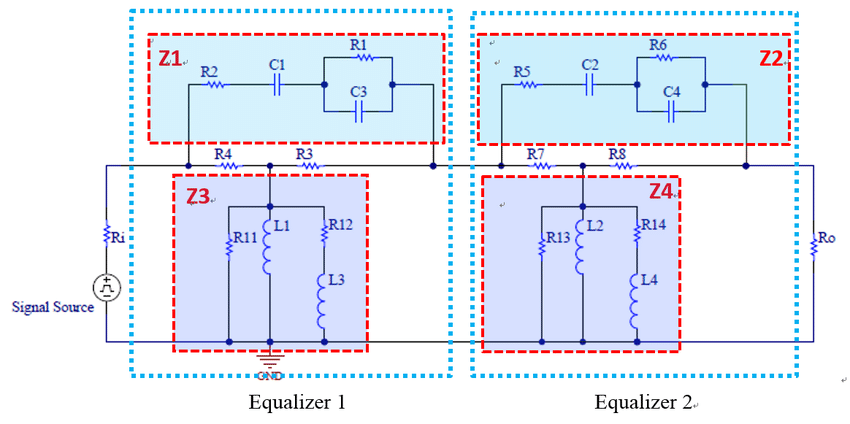
Gb/s real-time visible light communication (VLC) systems based on non-return to zero on-off keying (NRZ-OOK) using an LED is an emerging technology. A cascaded bridged-T equalizer network is necessary (Figure 4) to implement these systems. With the bridged-T circuit, the 3-dB bandwidth of the VLC system can be extended from 1 to 520 MHz. The system’s bit error rate is 7.36 × 10⁻⁴, and the data rate is 1 Gb/s at a distance of 1.5 m.
Lattice for grid-connected DERs
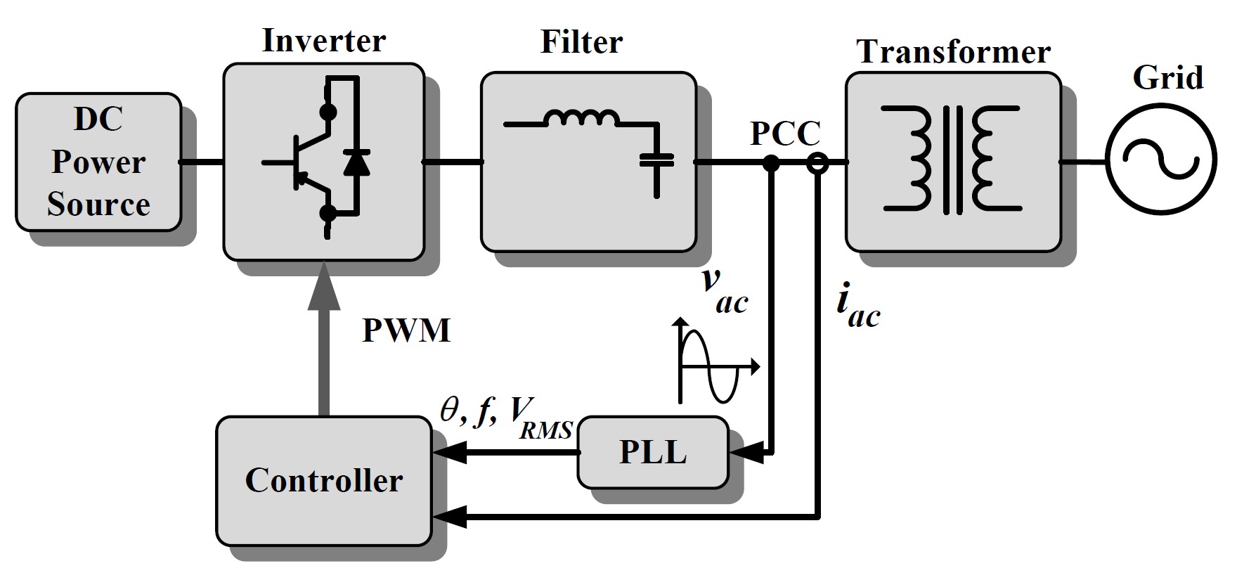
Accurate information about the phase, frequency, and amplitude of the voltages at the point of common coupling (PCC) is needed by the controller of single-phase grid-connected inverters for distributed energy resources (DERs). A phase-locked loop (PLL) is used for rapid synchronization with the grid that is necessary to meet the requirements of network codes and optimize inverter performance. The main task of the PLL is to detect real-time voltage information at the PCC accurately. A lattice all-pass filter can accurately determine the needed values, even in voltage harmonics, and generate an orthogonal voltage system for the PLL (Figure 5).
Summary
Equalizers can be used to linearize the performance of RF signal chains or to introduce nonlinearities into audio signal chains. They can be used to manipulate the signal chain’s gain, phase, or other characteristics. In addition to communications, RF, and audio systems, equalizers are used in various applications such as visible light communications and renewable energy systems.
References
Bridged T Delay Equalizer, Wikipedia
Comparative Analysis of Lattice-based All-Pass Filter and Second Order Generalized Integrator as Orthogonal System Generator of a PLL, Advances in Electrical and Electronic Engineering
Equalization (audio), Wikipedia
Gb/s Real-Time Visible Light Communication System Based on White LEDs Using T-Bridge Cascaded Pre-Equalization Circuit, IEEE Photonics Journal
Lattice Phase Equalizer, Wikipedia
RF/Microwave Equalizers: An Essential Ingredient for the Modern System Designer, Mini-Circuits