Part 1 of this FAQ explained the basic principle of the Wheatstone bridge. This part will take the bridge configuration into modern applications and go beyond basic resistance measurements.
Q: All this measurement via changing resistance or by measuring current seems very slow or static; how does it fit into today’s electronics?
A: First, many of today’s circuits, including those implemented by ICs, rely on determining when current flow is zero between an unknown and known resistance, for which the bridge s well suited. Also, the ability of the bridge to cancel out many internal errors is especially compatible when multiple resistors fabricated on a common substrate, or in ICs as matched, tracking pairs are relatively easy and inexpensive to fabricate.
Q: Is that all?
A: Absolutely not. A bridge amplifier can be used to electrically sense and amplify the current, and indicate zero with high precision. Note that the nonlinearities of this amplifier do not matter, since we are looking for a null. Only DC offsets and drifts matter, and these can usually be trimmed or calibrated out to a large extent.
Although the bridge can be used as a nulling circuit, it can also be used to measure changes in resistance via the current flow across the bridge legs. The amplifiers of modern electronics make this easy, as the change in resistance of the variable leg can easily be calculated from the current across the bridge.
Q: Any there other points of which to be aware?
A: There are two points to keep in mind when using the bridge to measure current and thus change in resistance of one of the legs. First, the relationship can be calculated, but it is not linear. Do the math of the resistance and ratio division, and you’ll see that a doubling of the current doesn’t mean that the resistance change has doubled. This non-linearity can be accommodated with by an analog circuit which has a complementary non-linear curve, by a digital look-up table, or by calculating current versus resistance.
Also, note that the measurement across the bridge is not grounded; it is “floating.” Even if the source battery or supply is grounded, that bridge measurement points are not. Therefore, any amplifier used to boost the bridge’s small output must be floating as well, meaning it must be a difference amplifier, instrumentation amplifier, or even an isolation amplifier. A basic grounded-configuration op amp will not work, but with modern ICs, this is a non-issue.
Q: Thus far we have only used DC to “excite” the bridge, and resistors as its legs–are we limited to those constraints?
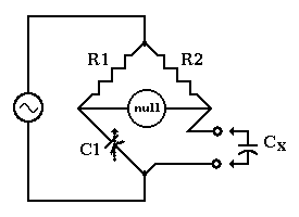
A: Not at all. The bridge can be excited with an AC waveform, and it can be used to measure unknown reactances (capacitors or inductors) or changes in those components. In fact, the bridge is used quite often this way, for same reasons it is used with resistors. The bridge does not need all four of the arms to be capacitors or inductors, Figure 1, as long as the ratio equations can be satisfied.

Q: What frequencies are used for AC excitation?
A: It depends on the application, but typically will be a few kHz to tens of kHz. At higher frequencies, parasitics may affect measurement accuracy, but often these can be calibrated out to some extent. Specially designed Wheatstone bridges are available for RF frequencies into the hundreds of MHz and even GHz. Excitation voltages are generally between 3 and 15 V; higher voltages lead to more accuracy to due higher SNR, but also induce more self-heating and result in thermal issues with the bridge legs, higher current consumption, and even reduced life for the elements of the legs.
Q: It seems that the Wheatstone bridge as a nulling unit is an instrument of the past…is this true?
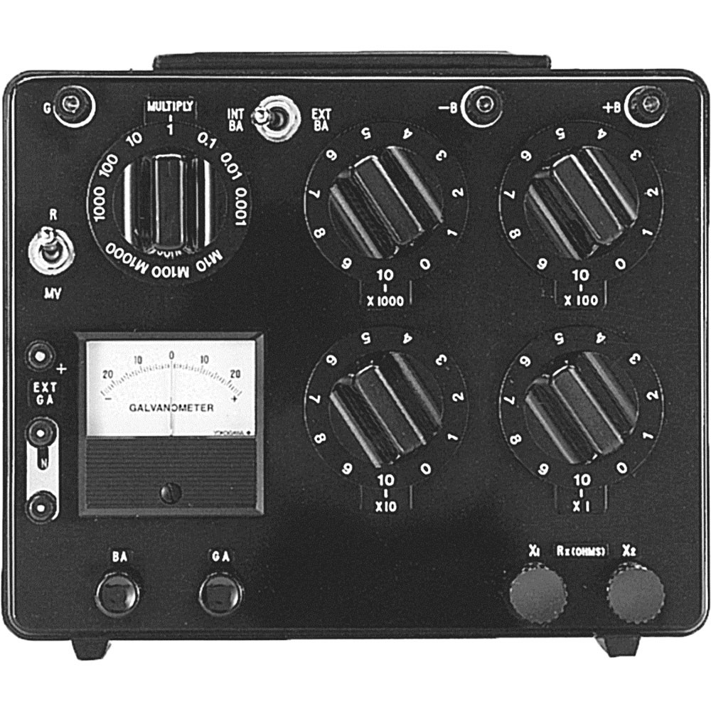
A: Yes and no. The bridge as a standalone unit is still used for precision calibration and measurement, and models are available from multiple vendors, Figure 2. Since they are entirely passive, they don’t have nonlinearities which affect their performance, except at the extremes of their range, and generally don’t go out of calibration as long as used within their operating limits.
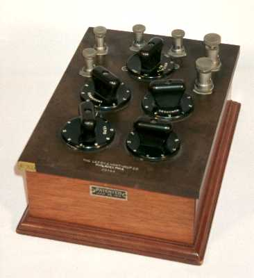
Prior to the development of analog and digitals meters, the Wheatstone bridge was a highly prized electrical lab instrument, built as a precision, carefully crafted unit and treated with respect just as a fine watch might be. If you go to almost any museum of scientific instruments, you’ll see Wheatstone bridges from the past and likely marvel at their construction, which blends electrical performance with elegant cabinetry and housing in many cases, Figure 3. The “museum-like website” at Kenyon College (Reference 6) has pictures and descriptions of many of these fine instruments, which are a “bridge” (so to speak) between instrumentation of the past and measurement of the 21st century.
Q: Final question: is there any relationship between the Wheatstone bridge and the H-bridge used in motor control?
A: Yes and no: they both have the same apparent topology, with two pairs of components between the power rail and ground, and the “load” in the middle, but that’s about it. The H-bridge is used to turn on/off the load by controlling the flow of current from rail to ground, while the Wheatstone bridge is used to find a null.
References
- NASA, “Wheatstone Bridge Circuit”
- Analog Devices, “Bridge-Type Sensor Measurements are Enhanced by Autozeroed Instrumentation Amplifiers with Digitally Programmable Gain and Output Offset”
- Analog Devices, “How to Stay Out of Deep Water when Designing with Bridge Sensors”
- Ohms Law Calculator, “Voltage Divider Calculator”
- Engineers Edge, “Wheatstone Bridge Circuit Equations and Derivations”
- Kenyon College, “Wheatstone Bridges”