Common mode rejection ratio (CMRR), also called common mode rejection (CMR), quantifies the ability of an operational amplifier (op amp) to reject common-mode signals. Common-mode signals are signals that appear simultaneously and in phase on both inputs. This FAQ begins by defining what CMRR is and how it’s quantified, reviews some design considerations related to CMRR, and closes with a brief discussion of how CMRR can be measured.
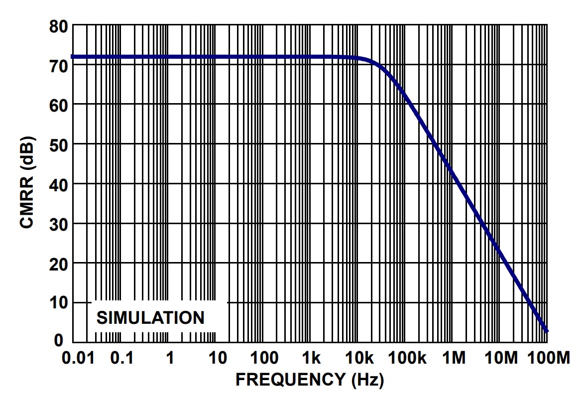
CMRR is quantified in dB and is defined as the ratio of the differential gain Ad over the common-mode gain Acm: CMRR = 20 log (Ad/|Acm|. The ideal value of CMRR is infinite, meaning complete rejection of any interference. To reject all of the noise signals the common mode gain must be zero, and from the equation, when Acm = 0, CMRR = ∞. In real op amps, Acm is never equal to zero, and typical CMRR values range between 70 dB and 120 dB, and at higher frequencies, CMRR declines (Figure 1). For example, if an op-amp has 60 dB CMRR and a 40 dB gain, a 10 mVpp common-mode signal at the input will result in a 1 mVpp signal at the output (10mV/1000*100 = 1mV).
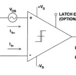
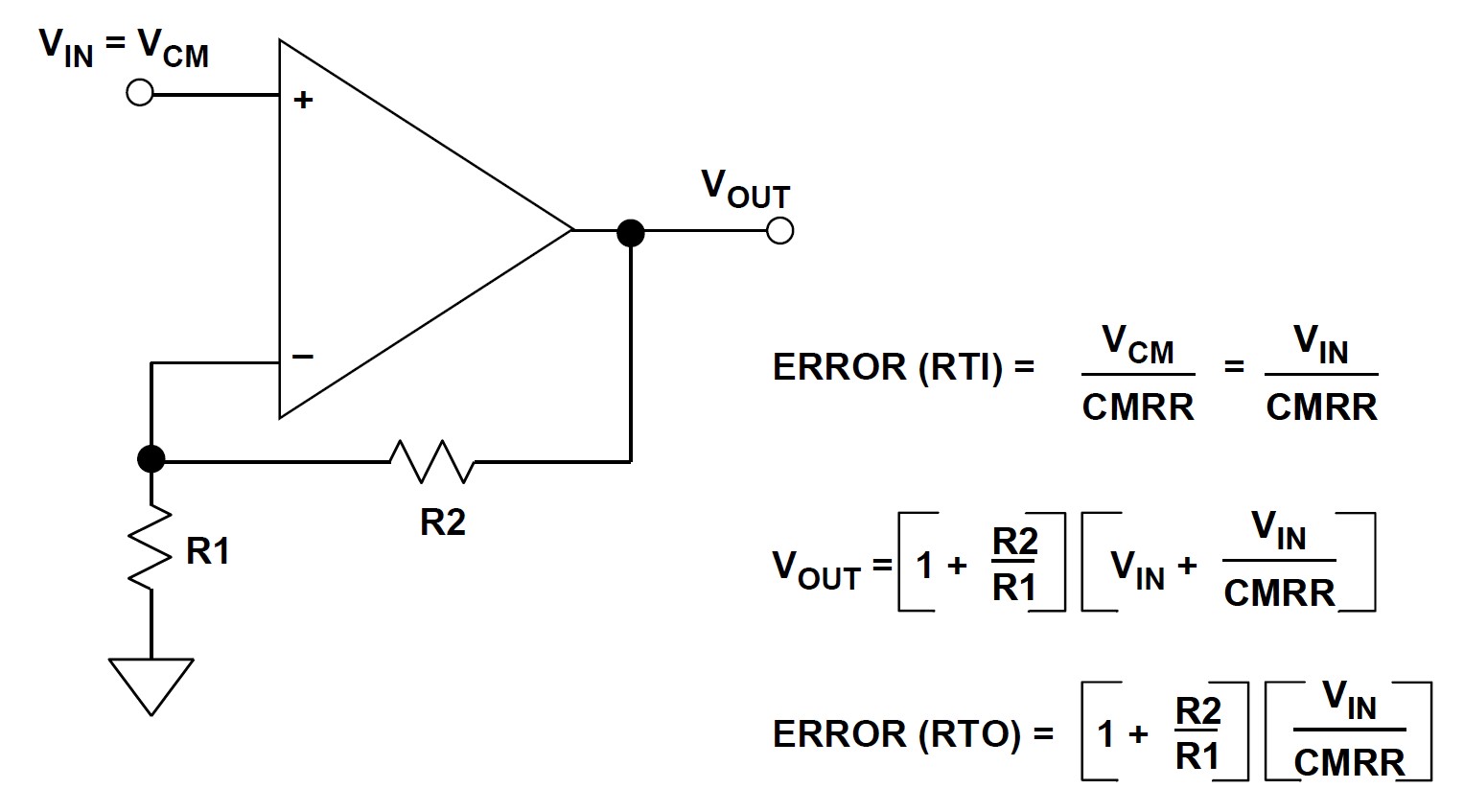
When an op amp is configured in noninverting mode, CMRR results in an output offset voltage error (Figure 2). Op amps used in inverting mode will experience lower CMRR error since both inputs are at ground and there is no dynamic common mode voltage.
A high CMRR is needed when a differential signal needs to be amplified in the presence of a large common-mode signal such as electromagnetic interference. A high CMRR is important when the signal of interest is a small voltage fluctuation superimposed on a (large) voltage offset. A high CMRR is needed with audio, video, and communications systems, such as voice and image recognition systems or wireless systems in noisy industrial environments. It is also important when relevant information is contained in the voltage difference between two signals, like audio transmission over balanced lines or serial communication like USB and CAN bus.
When an op amp is receiving a low-level and balanced signal over a long distance, such as an instrumentation cable in a factory or a long audio cable, CMRR is also important. In these cases, common-mode interference signals can be induced into the cable. Since the received signal is differential in nature, a high CMRR effectively eliminates the interference. Or, when an op amp is part of a bridge circuit, for example, with a thermocouple, the signal comprises small variations between two dc values. The op amp must be able to amplify the difference signal but reject the dc components of the bridge. That can be particularly important in noisy environments. The CMRR of the measuring circuit determines the attenuation of the noise and the fidelity of the measurement. Another example is current sensing circuits which are often implemented by measuring the voltage drop across a very small resistance shunt. The voltage across the shunt will be only a few millivolts and needs to be accurately measured in the presence of voltages that are several orders of magnitude higher.
CMRR and design considerations
Three design considerations when a high CMRR is needed include:
- Use of a precision op amp with a high CMRR over a wide operating voltage range can eliminate the need for calibration or trimming and ensure stable performance across a range of operating conditions.
- CMRR is influenced by imbalanced resistor values at the input terminals. Carefully balancing those resistors can help to improve CMRR. In addition, changing the input voltages can help improve CMRR with some op amp designs.
- Use of high impedance current sources or sinks on differential inputs produce more consistent performance than resistors to bias the differential pair.
Measuring CMRR
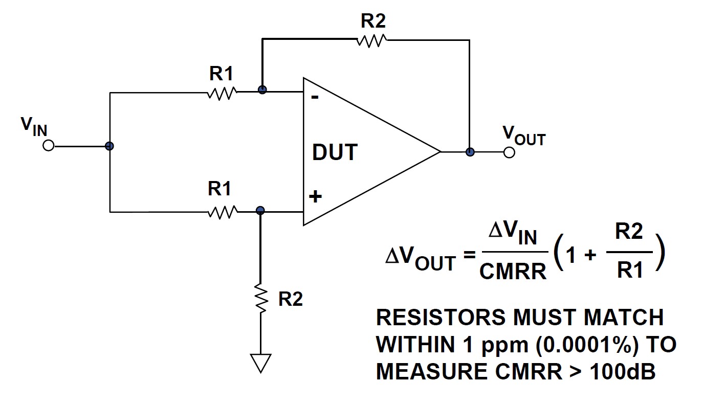
Several methods can be used to measure op amp CMRR. The most accurate method involves using a network analyzer. A simplified method uses four precision resistors to configure the op amp as a differential amplifier (Figure 3). The change in the output is measured as a signal is applied to both inputs. When using this method, the ratio match of the resistors is as important to the measurement as the op amp CMRR. A 0.1% mismatch between the resistor pairs will produce a CMRR of 66dB, no matter how high the actual CMRR of the op amp. Most op amps have CMRRs over 70 dB, limiting the practicality of this approach. To get useful results, a network analyzer is needed.
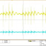
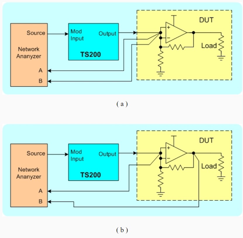
Combining a network analyzer with a modulated power supply unit can produce highly accurate CMRR measurements (Figure 4). The test is performed in two steps. First, the test setup needs to be calibrated. During calibration, the network analyzer input-A and input-B are connected at the op amp input, and the network analyzer sweeps over the frequency range to be measured. After calibration, the network analyzer input B is moved to the op amp output, and the network analyzer again sweeps over the test frequency range to measure the CMRR. As noted above, CMRR values can be voltage sensitive, so the test should be replicated over the range of common mode voltages from 0 to Vcc.
Summary
CMRR is measured in dB and quantifies the ability of an op amp to reject common-mode signals. Typical CMRR values range between 70 dB and 120 dB to about 100 kHz; at higher frequencies, CMRR declines. CMRR is an important op amp specification across a range of applications where a differential signal needs to be amplified in the presence of a large common-mode signal. In addition to specifying op amps with high CMRR, there are several design considerations that can maximize system performance. A network analyzer and a modulated power supply can measure actual op amp CMRR performance.
References
Standard mode rejection ratio, Analog Devices
Common mode rejection ratio, TiePie
Common-mode rejection ratio, Wikipedia
How to Measure Op-Amp CMRR, Accel Instruments
Op Amp Common-Mode Rejection Ratio (CMRR), Analog Devices