Signal chain management is important in various applications like medical imaging, 5G communications, advanced driver assistance systems (ADAS), and a range of consumer, industrial, and military devices. Filters, attenuators, and equalizers are some of the tools designers have available to optimize signal chain operation.
This FAQ begins by looking briefly at the definition of decibels (dB) and nepers (Np), two of the basic performance metrics for signal chain management; it then reviews the operation of and some uses for filters, attenuators, and equalizers.
A dB is a relative unit of measure and expresses the ratio of two values of a root power or power quantity on a logarithmic scale. It’s useful in discussing signal chains because signal strengths tend to vary logarithmically, not linearly.
When used to express a power ratio, a dB is defined as ten times the logarithm in base 10, a 10 dB change in level corresponds to a 10 X change in power. When used with root power quantities, a change in amplitude of 10 X corresponds to a 20 dB level change. The power and root power dB scales differ by a factor of two since power is proportional to the square of the amplitude.
In addition to being used for relative measurements, dB can express an absolute quantity based on a reference value. For example, when the reference value is 1 volt, the unit of measure becomes a dBV. A 1 Vrms signal would correspond to 0 dBV. The positive values of dBV represent voltages above 1 Vrms, and the negative values represent values below 1 Vrms. The dBV is often used in the audio industry since it can provide a good correlation with the sensitivity of the human ear. The dB unit often used in communications networks is decibel-milliwatts, dBm, or dBmW. It expresses a power level with reference to one mW.
Some applications refer to the Np instead of the dB. Np is based on natural logarithms in contrast with the use of base 10 logs for dB. The dB and Np are defined in the international standard ISO 80000.
Filters and filtering
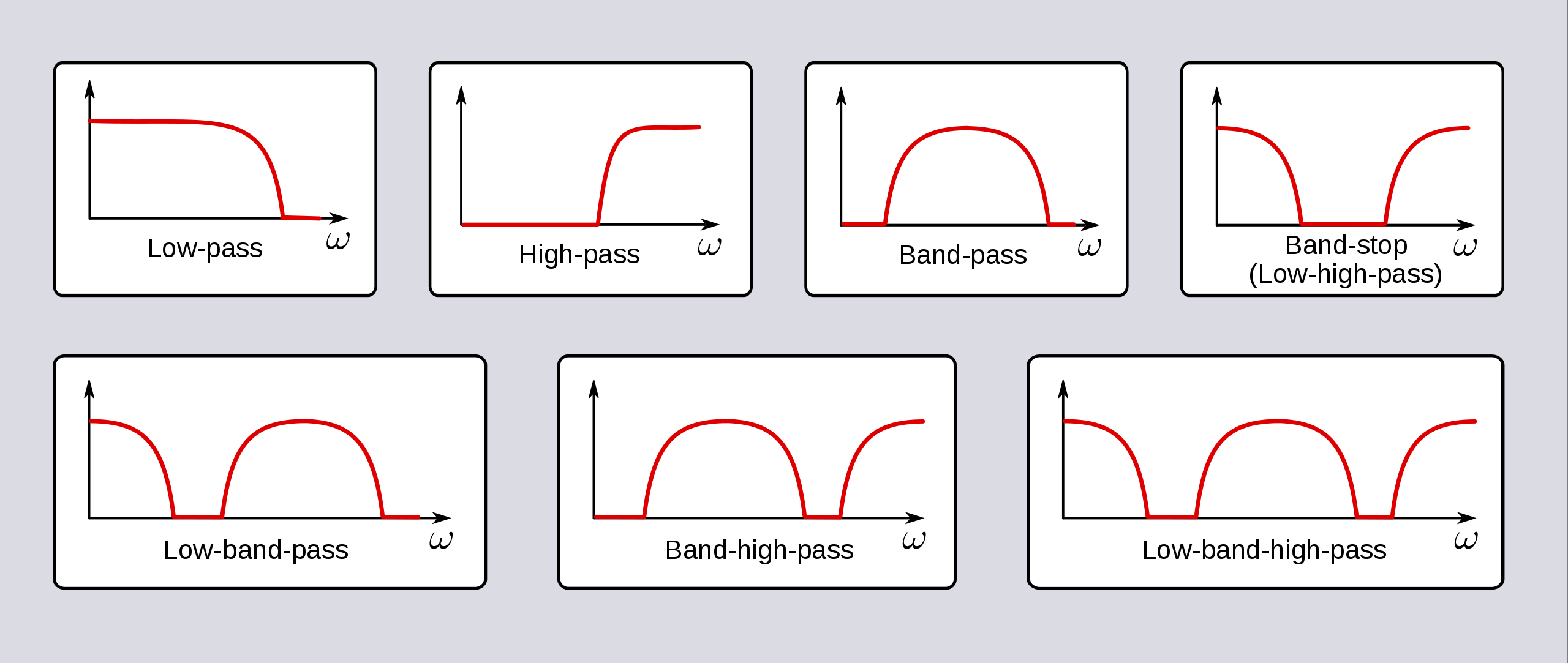
In signal processing, a filter is a device or process that removes or modifies some components or features from a signal. A filter partially or completely attenuates some aspect of a signal. Most often, this means removing some frequencies or frequency bands. The level of filtering is usually measured in dB. Passive filters rely on networks composed of resistors, capacitors, and/or inductors. Active filters add elements like operational amplifiers (op amps) for enhanced functionality. There are many types of filter configurations. Examples include (Figure 1):
- Low pass filters pass a band of frequencies below a cutoff frequency (FC) and significantly attenuate or block frequencies above FC.
- High pass filters perform the opposite function and pass frequencies above FC while attenuating frequencies below FC.
- Band pass filters pass a range of frequencies between lower and upper cutoff frequencies, FC1 and FC2, respectively, and attenuate all other frequencies. The band pass is defined as FC2 – FC1.
- Band stop or notch filters reject or attenuate a band of frequencies like FC2 – FC1 while passing frequencies above and below the band limits.
- All pass filters pass all frequencies without attenuation but introduce a phase shift or other characteristic into the signal chain without changing the magnitude of the frequencies.
Of course, filters and filter components are not perfect, and filter operation is subject to parasitics and other non-optimal characteristics. For that reason, higher-order filters have been developed that are more complex structures designed to compensate for the non-ideal natures of filter components. The higher the order of a filter, the more complex it is and the closer its behavior is to an ideal filter.
Signal attenuation
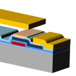
Attenuators are passive and dissipative two-port devices that reduce signal strength without disturbing the other characteristics of the waveform (Figure 2). Attenuation is measured in dB or Np. Attenuators can be used to lower voltages and improve impedance matching. They are used in RF, microwave, fiber optic, and audio networks.

Basic attenuator configurations include pi pads (π-type), T pads, and L pads. Pi and T pads are found in RF and microwave applications, while L pads are used for audio signal attenuation. RF attenuators can be balanced or unbalanced networks, depending on the line configuration they are used with. Attenuators designed for twisted pairs are balanced forms, while unbalanced form attenuators can be used with coax. RF attenuators have many uses reducing high power signals for test equipment, level control, and impedance matching. Optical attenuators serve similar functions in fiber optic systems. They are passive devices that lower optical power levels to protect sensitive receivers and other equipment; RF and microwave attenuators are made with thin-film and thick-film resistor technologies. Optical fixed attenuators are made using gap-loss, absorptive, or reflective technologies.
Fixed attenuators are the most common designs. They are available in various package styles, including surface-mount, waveguide, coaxial and connectorized designs. They are rated for operating frequency range, attenuation performance, and power handling.
Step attenuators are a variation of fixed designs. They typically offer a small number of fixed attenuation values that the user manually selects. For example, a step attenuator could have values from 0 to 40 dB in 0.5 dB increments. Some are digitally operated or programmable.
Mechanically variable attenuators are a variation on step attenuators where the attenuation can be varied smoothly over the specified range. They are primarily designed for test and measurement and engineering lab applications.
Variable attenuators are typically controlled with an external control signal. The control can be analog or digital. The attenuation varies smoothly over the specified range. Variable attenuators are used in system designs for matching networks, in automatic testing equipment, and production environments.
Equalizers are specialized attenuators.
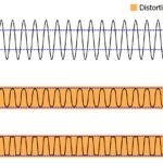
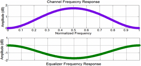
An equalizer is an attenuator with a frequency response that is not flat. For example, negative gain slopes have increasing losses at higher frequencies in microwave signal chains. It’s a characteristic common to coax cables, microstrip transmission lines, and even amplifiers. An equalizer with a positive gain slope can be added to compensate for and linearize the overall signal chain response. In addition, equalizers are often used in radar systems. Modern radars have multiple channels, and equalizers are used to cancel the interference caused by channel mismatches (Figure 3).
RF gain equalizers are categorized in several ways by operating frequency, powering, and the shape of the gain curve:
- RF gain equalizers are typically split into L-band and microwave frequency ranges. L-band gain equalizers operate in the 950 MHz to 2.15 GHz range, while microwave gain equalizers operate in the 2 to 20 GHz range. Both types exhibit low-order band pass filter gain characteristics.
- Active gain equalizers use an external power source, while passive gain equalizers don’t have an external power source. As a result, active gain equalizers can have positive gain characteristics since they amplify incoming signals. Passive gain equalizers don’t have an amplification function and have an insertion loss characteristic.
- Equalizers can be designed with a variety of gain slope shapes:
- Positive slope gain equalizers have an insertion loss that increases with frequency
- Negative slope gain equalizers have an insertion loss that decreases with frequency
- Positive/negative parabolic gain equalizers have a gain slope that becomes a parabolic shape, and the frequency increases.
Summary
Filters, attenuators, and equalizers are important elements in RF, microwave, optical, and audio signal chains. They are often specified by their gain or loss performance in terms of dB or Np. Filters are designed to change one or more characteristics of the signal being filtered. Attenuators are designed to keep the intrinsic properties of the signal unchanged (flat frequency response) but reduce the power level of the signal. Equalizers are specialized attenuators with a frequency response that is not flat.
References
Decibel, Wikipedia
Digital Equalization for Cancellation of Noise-Like Interferences in Adaptive Spatial Filtering, Circuits, Systems, and Signal Processing
Filter (signal processing), Wikipedia
Filters and Attenuators and their Applications, ThinkRobotics