Modern zero-drift amplifiers provide the extremely low drift and noise performance, needed for processing many optical biological, and physical-world signals near 0 Hz.
Contrary to what you might think, mechanical chopping is still alive and useful.
Given the outstanding performance of electronic components, using a high-performance zero-drift amplifier seems the way to go. That is done in most situations, but there are applications where using them can add to system complexity and actually create new error scenarios.
This is the case with optical links and associated measurements. It is certainly possible to convert an optical signal to an electronic one, then convey it to where the measurement is being made.
Measuring optical signals in the femtowatt (10-15) to nanowatt (10-9) range, however, is very difficult, as signal levels this low are soon lost in typical detector noise levels and swamped by background light. Narrowing the bandwidth by filtering or averaging will only provide a small additional reduction in the noise level.
Instead, there is a mechanical analog to the zero-drift designs that is used in these situations and pre-dates “electronics:” mechanical chopping. By using such a chopper with a lock-in amplifier, noise rejection can be improved by two to three orders of magnitude (sometimes more) while providing background-signal rejection that is several orders of magnitude higher than the noise rejection.
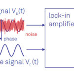
Lock-in amplifiers use homodyne detection to attain their outstanding performance. This detection has two requirements: a) the signal to be detected needs to be modulated and b) a pure, precise reference signal with the same frequency needs to be provided.
In the lock-in amplifier, the signal to be measured is multiplied by the reference signal and then integrated over time. By confining the measurement to a single frequency, detector noise is reduced drastically. In a similar fashion, background optical signals (primarily DC or line frequency) are similarly rejected by the lock-in amplifier.
The key to high performance with a lock-in amplifier is maintaining a precise match between the modulation frequency of the signal to be measured and the frequency of the reference signal. In these applications, an optical chopper is used to modulate the signal (Figure 1).
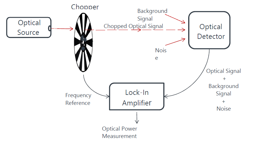
This optical chopper is conceptually simple; just a spinning disk that is divided into vanes and windows. The chopper disk is positioned in the optical beam path so that as it spins the beam alternately passes through the windows or is blocked by the vanes. The reference signal is easily provided by using an optical interrupt switch to sense the rotation of the vanes and windows. The reference signal provided by this technique will be a precise frequency match for the optical signal to be measured.
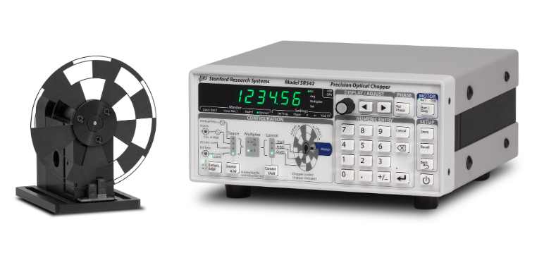
These chopper systems are widely used and are available from many suppliers of optical-electronic test and measurement equipment. The SRS542 Precision Optical Chopper from Stanford Research Systems, for example, provides chopping from 0.4 Hz to 20 kHz and has 50 ppm frequency accuracy (Figure 2).
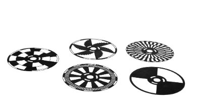
Just as gears with different numbers of teeth are used to span a wide mechanical dynamic range, chopping disks with different patterns are available to provide coverage over a wide frequency range (Figure 3). The metal blades are photochemically etched to provide tight tolerances for the blades to ensure low-phase jitter of the optically chopped signals.
Conclusion
Despite the move into ever-higher frequencies, there are still many test and measurement situations where the signals of interest are near zero hertz. To address their unique amplification needs, zero-drift amplifiers use chopping and auto-zero topologies to achieve extremely low levels of drift and nose. At the same time, the classic mechanically based chopper with a spinning disk still has a role, especially for optical signals.
EE World related content
Understanding the lock-in amplifier, Part 1: The sensing challenge
Understanding the lock-in amplifier, Part 2: The homodyne solution
Lock-in amps get AM/FM modulation option
Teaching instrumentation gets new filter options, lock-in amp
Squash 1/f noise with zero-drift amplifiers
New 45-V, zero-drift op amp features ultra-high precision and EMI filtering
Zero-drift, nanopower op amp works from 650 nA supply current
Zero-drift Amplifier Achieves Industry’s Lowest Voltage Noise
Tiny 3-MHz chopper op amps feature rail-to-rail input and output
Additional references
Analog Devices, “How to Use Zero-Drift Amplifiers in Wider Bandwidth Applications”
Analog Devices, Tutorial MT-055, “Chopper Stabilized (Auto-Zero) Precision Op Amps”
AZO Optics, “What is an Optical Chopper?”
Perkin Elmer, AN-1003, “Low Level Optical Detection using Lock-in Amplifier Techniques”
Ophir Optronics Solutions Ltd, “Working in the Basement: Measuring Signals Below the Noise Floor with a Lock-in Amplifier”
Stanford Research Systems, “SR542 — Low jitter optical chopper”