
Network elements must meet certain frequency, phase, and time requirements to ensure proper end-to-end network operation. Synchronization architectures defined by the O-RAN alliance dictate how Open RAN equipment can meet these requirements.
Open RAN continues to attract interest from service providers looking to reduce cost, improve competition, and drive technology innovation. The desire for a disaggregated and virtual RAN architecture has introduced more flexibility, competition, and openness to the 5G networks.
The O-RAN Alliance was formed in 2018 to standardize hardware and define open interfaces that ensure interoperability between vendor equipment. Protocols, architectures, and requirements for the control, user, and synchronization planes are defined in O-RAN.WG4.CUS.0-v10.00.
The S-Plane and accuracy
The synchronization plane (S-Plane) addresses network topologies and timing accuracy limits for the fronthaul network connection between the O-RAN radio unit (RU) and distributed unit (DU). The requirements for frequency, phase, and time synchronization follow the 3GPP recommendations and align with the ITU-T network and equipment limits. For time-division duplex (TDD) cellular networks, the base requirement for TDD cellular networks is 3 µsec between base stations, or ±1.5 µsec (G.8271) between the end application and a common point. More stringent accuracy requirements exist for equipment used with advanced radio technologies such as coordinated multipoint or MIMO. To meet these tighter network limits, equipment will need to meet the Class C (30 nsec) maximum absolute time error defined in G.8372.2.
Timing configurations
The S-Plane consists of four topologies for distributing timing through the fronthaul network (RU to DU). These configurations rely on a combination of time-based and frequency-based synchronization techniques. A primary reference time clock (PRTC or ePRTC) located in the network will provide a base time for each network element. The use of GNSS, precision time protocol (PTP), and a physical layer frequency source, most commonly Synchronous Ethernet (SyncE), ensures the RU reliably receives the frequency and, more importantly, the phase and time synchronization required to operate the network.
Figures 1 and 2 show the four defined configurations for supporting network synchronization in the Open RAN fronthaul network.
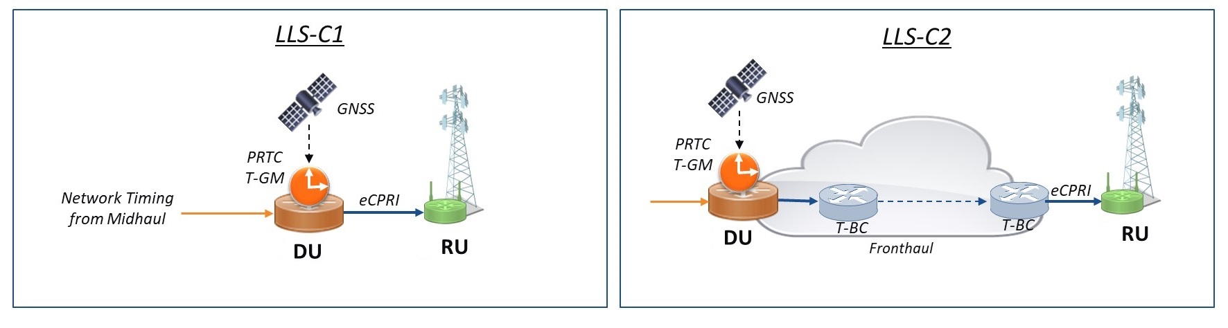
Figure 1. In these configurations, timing comes from upstream (left) or from T-BC’s in the fronthaul (right).
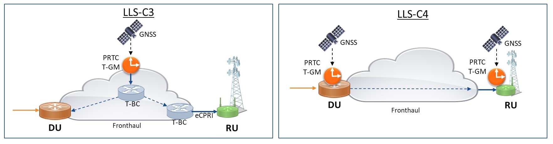
Figure 2. The DU and RU get time from a PRTC (left) while timing comes from GNSS through switches (right).
Configuration LLS-C1
Synchronization for the first configuration occurs through a direct connection between the DU and RU. The O-DU will receive network time from a precision real-time-clock/telecom grandmaster (PRTC/T-GM) that is either co-located with the O-DU or from a remote PRTC/T-GM located further back in the network.
Configuration LLS-C2
For configuration LLS-C2, the DU still receives network time from a co-located PRTC or one further upstream in the network. Network time passes from the DU through additional switches that reside in the fronthaul network. For best performance, these switches should comprise a fully aware (G.8275.1) network where each node acts as a telecom boundary clock (T-BC). Partially aware networks where one or more switches don’t participate in the filtering of PTP are also allowed. Depending on the type of fronthaul network, the type and number of hops present through the fronthaul network will limit the overall performance of the network. For example, a fully aware network comprised of Class C (30 nsec) T-BC’s can facilitate more hops than a fully-aware network comprised of Class B (70 nsec) T-BC’s.
Configuration LLS-C3
For the third configuration, both the DU and RU will receive network time from a PRTC located in the fronthaul network.
As with LLS-C2, network time can propagate through the fronthaul network via fully-aware or partially-aware switches. In some cases, the DU may participate as a T-BC in passing time to the RU.
Configuration LLS-C4
Configuration LLS-C4 is the most preferred and easiest to implement but potentially the costliest of the four topologies. In this configuration, the RU gets time from GNSS as a pulse per second (PPS) clock or from a co-located PRTC/T-GM. The sheer number of 5G NR sites and the location requirements of the GNSS antenna can make this a costly or impractical configuration to deploy. GNSS at the radio sites may also be more susceptible to spoofing or jamming, which can disrupt proper operation.
Equipment design
Like network deployments, the synchronization design of network equipment requires proper planning and design. To satisfy network synchronization limits, equipment will use a combination of timestampers, advanced phase lock loops (PLL), robust software for PTP support, and precision oscillators (Figure 3).
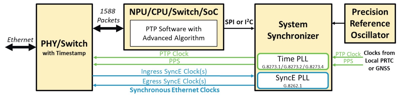
Figure 3. Network equipment uses a combination of PTP software, a system synchronizer, PLL’s, and a timestamper.
The first key piece of the design is the system synchronizer, which consists of several advanced PLLs. The synchronizer provides jitter and wander filtering for SyncE clocks, input reference-clock monitoring, hitless reference switching, and a numerically controlled oscillator for fine PPS/PTP clock control. The PLLs also provide bandwidths capable of locking directly to PPS clock sources.
Accurate timestampers, PTP software, and an advanced algorithm will manage PTP traffic and provide the tuning calculations needed to accurately track T-GM phase and time. Finally, the precision oscillator is critical to ensure proper holdover and overall performance parameters.
These building blocks are the same for the DU, RU, and any switch participating in timing distribution. The actual implementation of the functional blocks may differ depending on the use case. For example, the precision oscillator may vary depending on the holdover requirements for each network element. A DU needs more stability and must support longer holdover times than an RU. Because of this, RU designs may be able to use higher-end temperature-controlled oscillators (TCXOs) or mini-oven-controlled oscillators (OCXOs) while a DU may use a more expensive OCXO.
Improving timing latency
You can employ any of several techniques to improve overall time accuracy within a piece of equipment. These techniques range from basic design items such as placing the timestamper as close to the edge of the equipment as possible, to more complex system calibration for phase management within the system. The use of SyncE and more specifically the Enhanced Synchronous Equipment Slave Clock (eEEC), as defined in G.8262.1, provides a stable frequency reference that greatly improves overall phase performance for hybrid configurations.
When used with security protocols such as MACsec, take care to ensure that the encryption/decryption adds little or no delay to the timestamping function. Properly design and select the performance of the advanced algorithm and precision oscillator stability to provide the needed performance. For more complex designs, ensuring all timing components involved in the distribution of the PPS clock minimize input-to-output delay variation and output-to-output skew is critical to satisfy even the tightest equipment limits. Some synchronizers take advantage of calibration functionality that provides fine phase control measurements and adjustments. Additional compensation for phase error caused by the temperature and aging of the precision oscillator temperature can also be accomplished. You can use some or all these methods to ensure that equipment meets time and accuracy limits.
Initially, rural and private greenfield networks have been good launching points for deploying Open RAN. As more macro deployments begin to come online, providing high-accuracy network synchronization will be critical for delivering the performance that ultra-low latency applications and advanced radios technologies demand.
Darrin Gile is a senior technical staff engineer for Microchip Technology’s timing and communications business unit, with more than 26 years of experience in the semiconductor industry. For the past 20 years, he has held field applications and business development roles assisting clients with network synchronization and advanced timing applications. Mr. Gile specializes in customer engagements related to Synchronous Ethernet and IEEE-1588. He holds a Master of Science degree in electrical engineering from the Georgia Institute of Technology.