Peer-to-peer, engineer-to-engineer questions and answers from the EDABoard.com engineering community around analog ICs and analog design. Click the “Read more” link and follow the entire conversation and maybe add your two cents by logging in to EDAboard.com.
Cascading filter after a two poles Sallen-Key – Hello I have a Sallen-Key topology lowpass, as in the picture, which cuts at 40kHz. Now, this is an antialiasing filter after a DAC and before a power amplifier. I need to add a stronger filter, and the only way I have is to insert a filter after the existing one and before the power amp. How can I calculate the new filter? Read more
How to implement a transfer function with discrete components – I need to implement a second order transfer function in ‘s’ domain (having 2 poles, 1 zero and 2.5 DC gain) using transistors and discrete components. Since I have not done so previously, can anyone guide me how to do so? I did a search with the keywords ‘realise a second order transfer function, bjt’ but ended up with papers on filters etc. Read more
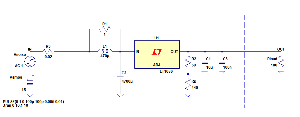
Better design for SMPS post regulator filter circuit – For minimizing SMPS ripple and especially noise, I’m trying to make a small interface which is a post regulator cascaded after an LC filter. The topology can be seen in the circuit I have drawn in LTspice. Here is my circuit in question(the one inside the dashed box is the filter). Read more
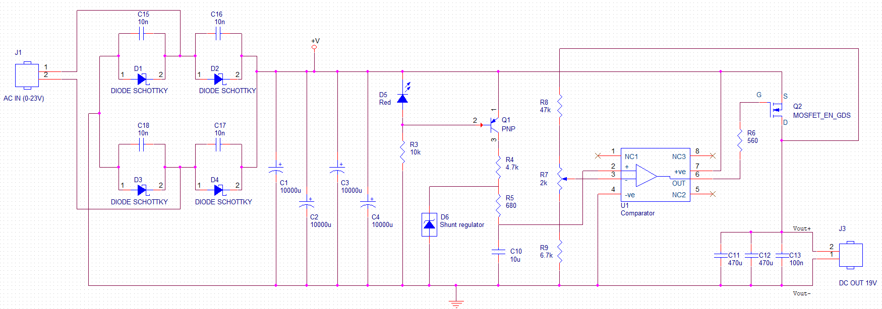
AC/DC converter explanation – I have reverse engineered the attached circuit from an old power supply, I was wondering how the comparator works? Can someone help me figure out how they did the calculations? I really want to get rid of the potentiometer (R2) which is used to tune the output and get 12v instead of 19v. Read more
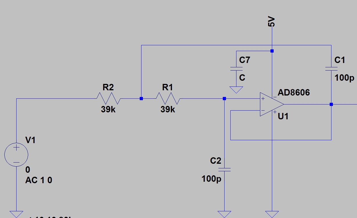
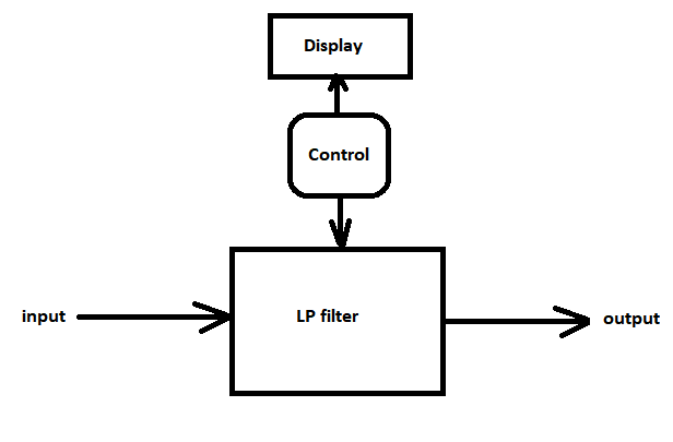
Quick way for an adjustable low pass filter – I want to build an adjustable low-pass filter for 0 to 10 kHz range as a general purpose but especially to be used as an anti-aliasing filter. One should be able to adjust the cut-off frequency of the filter by turning a knob and be able to see the adjusted cut-off freq. on an LCD or any indicator(otherwise without an LCD he will never be able to know what the adjusted cut off is). Here illustrates the basic idea:
LOOP GAIN’s phase and gain margin – Starting with an open loop system, you specific frequency gain and phase response plots. If you provide negative feedback, then that plot then gets split in half. The top portion is the loop gain, and the bottom portion is the closed loop system response. When you do stability analysis, it is optimizing the phase and gain margin of the loop gain response, but what does that do to the closed loop response plot? Read more
LDO voltage regulator – I want to Design an LDO with voltage 1.5 V and load current of 100 mA. I am not able to decide:
1. what value of output capacitance will be good and if I will need a bypass output capacitor. I am using an input of 1.2 V. If I use ceramic type capacitor,
2. what is the ESR value. Kindly help me with capacitor value and corresponding ESR and ESL values. I am thinking of driving the PMOS as pass transistor using single stage op-amp and a source follower stage.
3. Also what value of Quiescent current will be okay? Read more
Gyrator circuit discussion – What do you guys think about the following gyrator circuit? Anyone up for a discussion regarding the MOSFET sizing? Read more

Electronics system design – I would like to get your opinion on the best books or courses to study system design in electronics. And by that, I don’t mean Signals and Systems kind of books or Circuits books. Rather material that talks about designing specifications. Read more
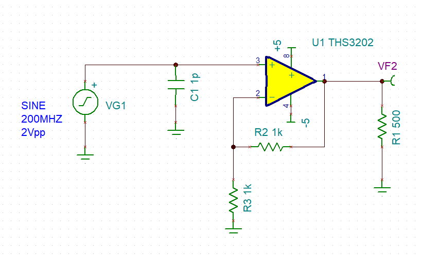
Understanding bode plot characteristics – I have a circuit where I try to understand how the bode plot works. Bellow is the schematic; the opamp circuit has a Gain of 2. Read more