(editor’s note: Intrigued by the problem? Have a question or another solution? Then click the “Read more” link and follow the conversation on EDAboard.com or log in to EDAboard and participate in the analog IC forum threads.)
LM386 low noise (hiss) alternative? – I am building a direct conversion (regenerative) receiver that is followed by this amplifier schematic set at max gain. The volume is good on my headphones, but there is too much noise. I confirmed that the noise is mainly from the audio amplifier because I disconnected it from the rest of the receiver and the noise is still there. Can you please suggest an alternative with a very low noise and high gain, so that the phones are driven comfortably but with low noise? Read more
Discrete op amp design – I’m designing a discrete op amp and having trouble reaching the gain values. The highest I can get is around 200. What tricks do I have at my disposal for raising the gain more? It seems to distort if I try to raise resistor values. Read more
Inverter for charging electronic devices – I made an inverter circuit to charge laptops and mobiles and I got 150v AC output. The problem with my circuit is that when I connect my circuit with my laptop charger it’s charging but frequently disconnecting. Read more

How to design 5V/12V SMPS – How should we start to design a power supply for a circuit with 12V/5V, 5A/10A? Read more
How to calculate the overall transconductance of an OTA circuit in Cadence – Can anyone help me in plotting the overall transconductance of an OTA (Gm) circuit in Cadence step by step? Do I have to do the AC analysis or DC analysis? Read more
Transistor biasing problem – I have a transistor that works at active mode. The base input of the transistor is about 0 V to 10 V. The collector is connected to the 24 V. The emitter output is about 0.5 V to 9.5 V. But I want the emitter output to change from 0 V to 24 V. The current of this voltage is about 100mA. How can I change my circuit for changing from 0 V to 24 V? Read more
![]()
How does a sample hold amplifier work? – I have a few questions regarding the following: “StrongArm Latch inverters (upper left and upper right) are loaded by each other, the three central PMOS reset transistors, and the next stage. Thus, the fanout (output to input capacitance) of the inverters is greater than one, and greater than two in any practical implementation. Consequently, a lower limit on the sampling time constant of the latch is roughly a fanout-of-2 delay or 0.4 FO4. In simulation, a StrongArm latch has a sampling time constant τ = 0.6 FO4, compared to the target of 0.3 FO4 . The regeneration rate, and thus the sampling time constant of the StrongArm latch,
varies with the input common mode (which changes the current supplied to the cross-coupled inverters), making it unsuitable for accurate, high bandwidth sampling.”
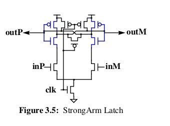
1) Is the CLK going low then the latch will latch the data?
2) what’s regeneration mean?
3)f an-out -2 delay or 0.4FO4 . What does that mean? Read more
Op amp with zero output voltage low – I am working on an instrumental device with a single supply. I need an op amp with zero output when it is in the low state. I mean VOUT-VSS=0V or at least below 5mv at 1mA. Is there any chip providing this? if not, is there any method to compensate deviation? Read more
High-frequency signal conditioning – Does anyone have any ideas about this signal conditioning circuit?

Signal source: KA3525 PWM controller IC.
Frequency: 39KHz
Signal is driving a N-Channel MOSFET directly.
What is the explanation of this signal conditioning circuit? Read more
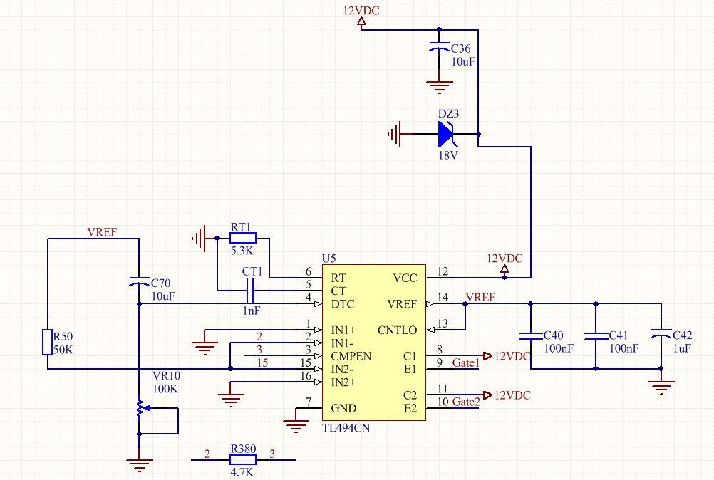
Problem with output PWM waveform of TL494 – I want to adjust TL494 for one open-loop SMPS with 45% duty cycle and 100khz PWM on the output. But there is a problem with the output PWM waveform (pin9 & pin10). Rise time is about 500ns and fall time is about 2.5 us. How can I correct the fall time? I think it is too high. Read more