
I have touched on light sensing methods and the amplification of the signals from them in the past, but at a more fundamental level, how do you choose one? What parameters are important? The answer depends, among other things, on the light source (focused or not), the amount of light and its color.
Focused or diffuse light source
It’s quite a significant factor in the choice of photodiode and part of the reason that large area devices exist. If you are trying to measure a diffused light source, then a larger area device will capture more light. More light equals more signal. The other option is to focus the light source on a small area if possible — then a smaller photodiode could be used.
The sensitivity of a photodiode is normally quoted in A/W.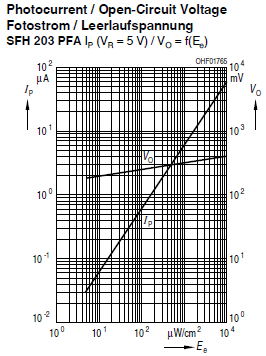
This curve shows the output current versus light power density for the Osram SFH203. Peak sensitivity is 0.62A/W so you can see 0.06µA at 10µW/cm2. It is a straight line because the relationship is linear. The photodiode has an active area of approximately 1mm2. 10µW/cm2 will only put 0.1µW of light on a 1mm2 detector so the 0.06µA is about what you would expect. If the sensor was 10cm2, then you would have 100 times the current because you would have 100 times the area.
The disadvantages of large area sensors include higher cost, higher leakage, higher dark current and higher capacitance (which makes them slower). One way around those issues for some applications is to focus your light source where possible. If you had a 10cm2 lens and used that to focus the light onto a 1mm2 detector, you would have the same signal as a 10cm2 detector. This can make a massive difference to the sensor size/cost/speed/dark current compared to a large area photodiode. Detectors sometimes quote an equivalent noise power and a signal detection limit. These can be useful, but it is often your amplification circuitry and load resistance that limits the lowest signal you can detect. To decide if you have enough light you need to know the noise of your amplifier and the bandwidth you are interested in (and will limit your circuitry to).
If your signal was 10µW/cm2 on a 1mm2detector like the SFH203, as mentioned above, you would have 60nA of signal. Assuming you had a transimpedance amplifier (or merely a resistive load) with a transimpedance of 1M ohm and bandwidth of 1MHz, the thermal noise at room temperature of the resistor would be 128µV RMS from the resistor alone. Your 60nA of signal would, therefore, be impossible to see. In reality, the noise would probably be even higher. So, something would need to be changed to measure a signal in that scenario.
You could reduce the bandwidth. A 1Hz bandwidth would reduce the noise to 128pV RMS so now you would easily be able to measure the signal. The bandwidth is an important factor in designing any analog circuits, and a light detection circuit is no exception.
Angle of incidence
The angle at which the light hits the detector will affect the sensitivity. The peak sensitivity of a photodiode is usually quoted with the light incident at right angles to the detector surface. The sensitivity of the detector will typically drop off with a cosine law so at 45 degrees the signal will have dropped to 71% of the peak value. However, that is for an unpackaged detector. In the package, the refraction caused by the package can improve the situation if it is plastic packaged with the molding in contact with the detector.
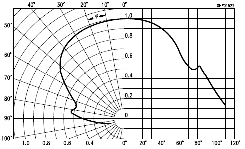
Here you can see that the SFH203 only drops to around 88% of the peak value at 45 degrees. This is about right if you look at Snell’s law of refraction. Assuming the plastic has a refractive index of 1.5, light at 45 degrees to the normal will only be at 28 degrees inside the plastic. cos(28 deg) is 0.88 i.e. 88% of the peak light value.
The situation would be different if you have a device in a metal package with a glass window because the incident angle will be 45 degrees on either side of the glass window in this example.
Effect of wavelength
Photodetectors have a peak sensitivity relative to the wavelength of the incident light. For silicon devices, this peak is typically around 900nm. At other wavelengths, the sensitivity will be lower so at 400nm it might only be 20% of the value at 900nm. Alternative materials such as InGaAs allow detection of wavelengths up to 2000nm or more. There are UV enhanced silicon detectors which will work down to 200nm such as the Hamamatsu S1226/1336 shown below.
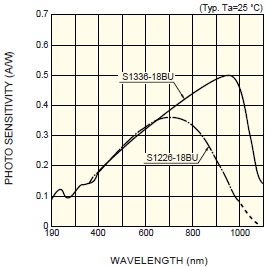
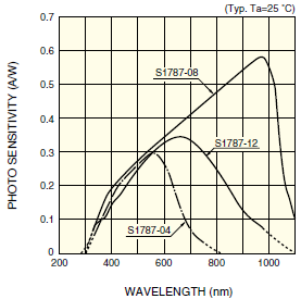
You can see the strange humps in the response below 400nm. Compare that with a device that is not UV enhanced such as the Hamamatsu S1787 series.
Leakage and dark current
Leakage and dark current often isn’t a problem with small area detectors and high light levels but can be a problem with large area detectors. Leakage usually has more than one component resistive and the leakage of a reverse biased diode. Either could dominate depending on the actual device, so you need to check the curves to make sure it won’t be a problem. The amount of reverse biasing is often a significant factor so for low leakage with large area devices you might run it at zero bias. Note that zero bias is where the photodiode capacitance will be highest and so the detection will be the slowest. You also need to be careful of operating temperature because the leakage due to the reverse biased diode is very sensitive to high temperatures, increasing tenfold every 25C in the case of the SFH203.
