A standard system requirement is to use the result of a simple “A vs. B” comparison as a basis for decision-making. For example, if the temperature is above a setpoint, turn the heat source off; and if the temperature is below that setpoint, turn the heat source on. Or perhaps there’s an alarm to sound if some critical parameter goes beyond a threshold, such as excessive speed.
Q: How is the comparator function implemented in analog circuitry?
The comparator circuit element which does this is conceptually simple. It has two inputs, one of which is the setpoint or desired reference (threshold) voltage and may be a fixed value, or user-adjustable, depending on the design, Figure 1. The unknown input-signal voltage, such as a temperature reading, is continually compared to the setpoint; if this input is greater than the setpoint, the output goes high; if the input is less than the input, the output goes low.

Q: To what is the output of the comparator connected?
It depends, of course, on the application and the system architecture. In some mostly-analog designs, or ones where there is a need to minimize issues with software interaction and associated risk, the comparator out may be directly connected to the function it controls, such as a heater element control. In most designs, however, the output is either scanned(checked) periodically by the processor (of a programmable logic controller or microcontroller system) or it is used to generate an interrupt to the processor. Once the processor-based system sees the comparator output state change, it initiates the action which it is programmed to do.
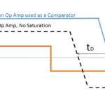
Q: What’s the difference between a conventional op amp and a comparator?
A comparator is a specialized operational amplifier (op amp) optimized for high gain, differential inputs, and a very nonlinear output state of either high or low. The desirable attributes of an op amps such as low bias current, low offset, and high linearity are not needed for a comparator, which instead needs fast response and stable performance when the two input signals are very close to each other in value. This, while there are general similarities, a comparator is better suited for the role, although in some cases a standard op amp can be used (see FAQ: Should I use an op amp as a comparator?).
Q: What else does a practical, useful comparator function require?
In a word: hysteresis. This is because a “perfect” comparator function actually has some negative aspects. Consider this scenario: the unknown signal is very close to the setpoint threshold. As it moves up and down a tiny bit, the comparator output goes from high to low and back continually. The result in constant “flickering” or “chattering” of the output, when the unknown signal is around the setpoint. Not only is this annoying (as in the case of a home-heating system or air conditioner) but it causes noise, premature wear-out of valves, mechanical fatigue, and other undesired consequences.
Further, even if this chattering was not considered to be a problem (a rare occurrence), a perfect comparator would be a problem because there is always electrical noise on the signal, and this noise would cause random high/low action on the comparator output.
Q: What does hysteresis do?
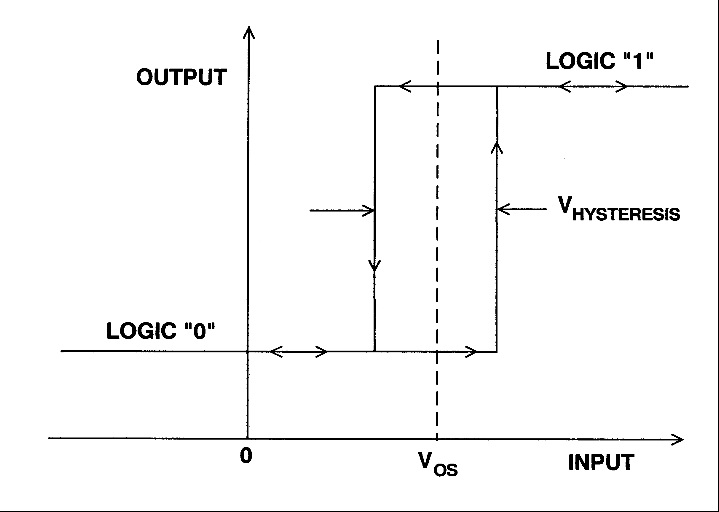
Hysteresis establishes a buffer zone around the trip-point threshold during which the output does not change from its previous value, depending on the direction of signal change. It works like this, Figure 2: assume the input is below the setpoint, so the output of the comparator is low. As the input signal increases, the comparator output does not change and go high until the input is “a little” above the setpoint. Now look at the reverse case, when the input is above the setpoint and the comparator output is high. As the input decreases, the output of the comparator does not change state until the input is a little below the setpoint.
Q: How is hysteresis implemented using analog circuitry?
It’s relatively simple and is done with some fixed resistors placed around the comparator, Figure 3. In cases where the amount of hysteresis needs to be changed, variable resistors (either adjusted manually set or digitally settable ones) can be used.

Q: What’s the “right” amount of hysteresis?
As in most engineering situations, the answer is: “it depends”. A smaller hysteresis zone means more tighter and more-accurate control, but also more on/off chattering due to minute signal changes and electrical noise. A wider zone means the on/off chatter is reduced, and noise immunity is increased, but at a cost in output accuracy. For example, a home gas oven with standard hysteresis can easily have a temperature swing of ±20°F around the user-defined setpoint; a laboratory oven would be designed with a much-smaller hysteresis band, such as ±1°F, but would have more on/off cycling of the heating element.
Q: Are the comparator function and hysteresis always implemented via analog components?
No. In cases where the input is changing very slowly, the system processor may instead read the digitized version of the input signal, compare it in software to the setpoint, and decide if the output action should represent the high or low state. The amount of hysteresis can then set entirely in the software, which adds to flexibility. Using a digital approach and software-based comparison and hysteresis is practical for slowly-changing signals and low sampling rates. But becomes difficult and a system-resource burden as the signal of interest reaches into the hundreds-of-kHz range and higher, and is very difficult to implement for signals in the MHz range. In contrast, an all analog comparator can easily be designed for tens of MHz and higher using standard components.
Reference
Analog Devices MT-083 Tutorial, “Comparators”